
Related Manuals for Bender MID Series


Summarization of Contents
1. Introduction
1.1 Isolated Power Panels
Provides isolated, ungrounded power to electrical systems in operating rooms and critical areas.
2. Safety Instructions
2.1 General Safety Warning
Only qualified personnel should operate. Turn off power before service. Follow codes.
2.2 Using This Manual
Explains safety symbols like DANGER, WARNING, CAUTION for user guidance.
3. Model Types
3.1 MIP / MIE Series Isolated Power Panels
Single-system, single-output-voltage panels; MIP for <=10 kVA, MIE for >=15 kVA.
3.2 MIC Series Isolated Power Panels with Circuit Control
Single-system, single-output-voltage panels with programmable control for up to 12 circuits.
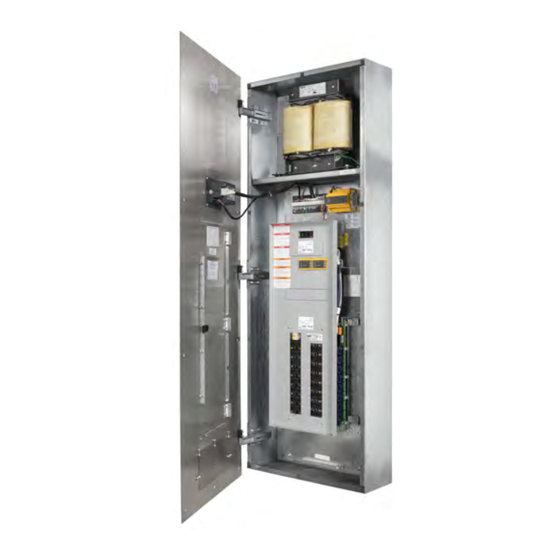
3.3 MID Series Dual Output Voltage Isolated Power Panels
Dual-output voltage system for simultaneous power to normal and high voltage equipment.
3.4 MIX Series Dual System Isolated Power Panels
Two MIP series interiors installed side-by-side in a common enclosure.
4. Components
4.1 Backbox Package
NEMA Type 1 galvanized steel backbox, designed for flush or surface mounting.
4.2 Front Trim Package
Stainless steel front trim with door, hidden hinges, and key lock for access.
4.3 Isolation Transformer Kit
Includes transformer, mounting hardware, primary/secondary breakers, and sub-plate.
4.4 Interior Package
Factory-wired sub-panel with distribution panel, ground bus, LIM, and optional accessories.
4.5 Circuit Breakers
Two-pole, thermal magnetic circuit breakers; sizing and quantity vary by panel model.
4.6 Line Isolation Monitor (LIM)
Monitors system impedance to ground, calculates total hazard current, and provides alarm.
4.7 Fault Location (EDS) Kit
Optional accessory to identify specific circuit contributing to total hazard current alarm.
4.8 Receptacle Kit
Provides NEMA type receptacles and/or hospital grade ground jacks accessible from the front trim.
4.9 Load Monitoring
Systems for full system or branch circuit load current monitoring.
4.10 Accessories Package
Refer to applicable documentation for any additional accessories included.
5. Receiving, Handling, and Storage
5.1 Receiving
Inspect equipment upon delivery, file damage claims, verify packing slip.
5.2 Handling
Use suitable equipment for lifting and transporting due to heavy load.
5.3 Storage
Store in dry locations, do not stack, do not lean front trims against walls.
6. Pre-Installation Requirements
6.1 General Requirements
Review codes, standards, and project requirements before installation. Minimize leakage current.
6.2 Support Requirements
Ensure proper structural support. Minimum load bearing requirements listed by type.
6.3 Size Requirements
Verify backbox dimensions and wall space availability before installation.
7. Installation
7.1 Considerations
General considerations before proceeding with installation steps.
7.1.1 Distance From Finished Floor
Table for allowable distances between bottom of panel and finished floor.
7.1.2 Available Conduit Areas
Figures showing shaded areas as allowable conduit locations.
7.2 Mount Backbox
Secure backbox to rigid support using 5/16" fasteners. Avoid over-tightening.
7.3 Install Conduit
Install metallic conduit per NEC Article 517.13. Ground all conduit, stubs, and connectors.
7.4 Install Interior
Align and fasten interior assemblies to threaded studs on backbox using 5/16" hex drive.
7.5 Remove Interior Deadfront
Remove four interior deadfront screws to detach the deadfront panel.
7.6 Install Breaker Kit
Install breaker kit if not factory-installed. Ensure model numbers match.
7.6.1 Components
Lists components of the breaker kit: bracket assembly and sub-plate.
7.6.2 Install Breaker Bracket Assembly
Attach breaker bracket assembly to interior backplate using #10-16 screws.
7.6.3 Install Breaker Sub-Plate
Fasten breaker sub-plate to interior deadfront using #6-32 flange nuts.
7.7 Install Transformer
Install transformer using provided vibration pads and mounting hardware.
7.7.1 Vibration Pads and Mounting Hardware
Instructions for installing vibration pads and mounting hardware for transformers.
7.7.2 Mounting
Place transformer on shelf or studs, orient for wiring leads. Handle heavy transformers with care.
7.8 Wiring
General wiring information. Disconnect power. Follow codes. Refer to wiring diagrams.
7.8.1 General Instructions
General wiring information. Disconnect power. Follow codes. Refer to wiring diagrams.
7.8.2 Transformer and Incoming Power Wiring
Connect incoming power feed, ground conductor, and transformer leads per diagrams.
7.8.3 Branch Circuit Wiring
Use specific wire types, keep conductors separate, minimize length. Terminate at breaker or contactor.
7.8.4 Grounding
Connect all ground conductors to the panel's ground bus. Bond systems if necessary.
7.8.5 Accessories / Add-On Kit Wiring
Refer to respective installation manuals for additional equipment wiring.
7.9 Wiring Diagrams
Wiring diagrams for MIP, MIE, and MIX series panels. Excludes accessory connections.
7.9.1 MIP, MIE, and MIX Series
Wiring diagram for MIP, MIE, and MIX series panels.
7.9.2 MIC Series
Wiring diagram for MIC series panels, including PLC, selector, and terminal block connections.
7.9.3 MID Series
Wiring diagrams for MID series panels, showing low and high voltage sections.
7.10 Reinstall Interior Deadfront
Align and mount the interior deadfront panel after internal work is complete.
7.11 Install Front Trim
Install stainless steel front trim, ensuring compatibility with the backbox.
7.11.1 Install U-Type Retaining Nuts
Place u-type retaining nuts over backbox mounting holes before attaching front trim.
7.11.2 Mount Front Trim
Lift and align front trim, mate hinge fittings. Handle with care due to sharp edges.
7.11.3 Install Line Isolation Monitor
Position LIM display through front trim cutout and secure to front trim with #6-32 flange nuts.
7.11.4 Install Transformer Heat Shield (MIX Series Only)
Slide heat shield into backbox slots and secure with #10-32 hex screws.
7.11.5 Install Lower Front Trim (MIX Series Only)
Align and secure the lower front trim using #2 phillips-head screws.
7.11.6 Install Restraining Lanyard (MIX series only)
Attach lanyard to backbox to prevent damage to LIM harness when opening front trim.
7.11.7 Connect Line Isolation Monitor Harness
Connect the 15-pin and 12-pin LIM wire harness from the connector plate to the LIM.
7.11.8 Close Front Trim
Fully close front trim and secure with Phillips truss-head screws in a star pattern.
Need help?
Do you have a question about the MID Series and is the answer not in the manual?
Questions and answers