Bender MIP Series Manual

Bender MIP Series Manual

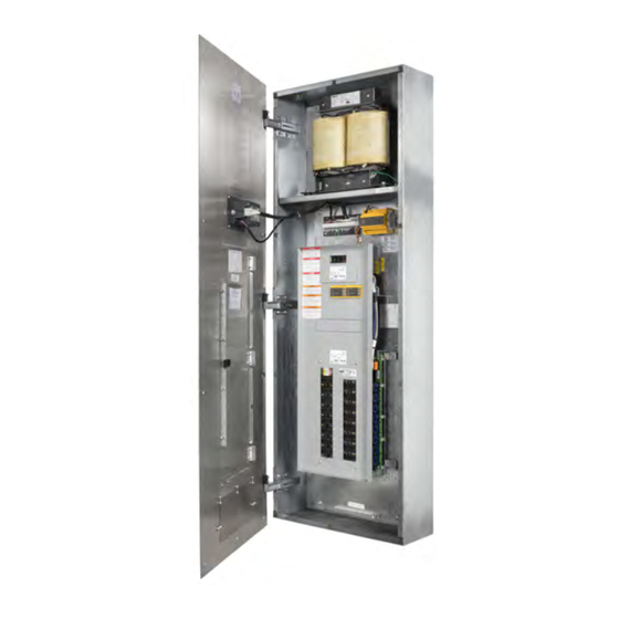
Isolated power panels for healthcare facilities
Table of Contents

Advertisement

EN
Manual
T M
Isolated Power Panels
For Healthcare Facilities
NAE209501-2 / 02.2019

Advertisement

Table of Contents
loading

Summary of Contents for Bender MIP Series

  • Page 1 Manual Isolated Power Panels For Healthcare Facilities NAE209501-2 / 02.2019...
  • Page 2 Toll Free: 800-356-4266 Phone: 610-383-9200 Fax: 610-466-2071 E-mail: info@bender.org Canada: 5810 Ambler Drive, Unit 1 NAE209501-2, 02.2019 Mississauga, ON L4W 4J5 Toll Free: 800-243-2438 Phone: 905-602-9990 © Bender Inc. Fax: 905-602-9960 E-mail: info@bender-ca.com All rights reserved. Content subject to change. Web: www.benderinc.com...
  • Page 3: Table Of Contents

    5. Receiving, Handling, and Storage ..........16 Receiving.................... 16 Handling ..................... 16 Storage....................16 6. Pre-Installation Requirements ............17 General Requirements..............17 Support Requirements..............18 Size Requirements ................18 7. Installation ..................19 Considerations ................. 19 IP Panels © 2018 Bender Inc. All Rights Reserved...
  • Page 4 7.10.5 Install Lower Front Trim (MIX Series Only)......41 7.10.6 Install Restraining Lanyard (MIX series only)......41 7.10.7 Connect Line Isolation Monitor Harness ........ 42 7.10.8 Close Front Trim ................42 IP Panels © 2018 Bender Inc. All Rights Reserved...
  • Page 5: Introduction

    1. Introduction 1. 1 Isolated Power Panels Bender isolated power panels provide isolated, ungrounded power to electri- cal systems in operating rooms and other critical areas in healthcare facilities. Isolated power systems allow for early detection of hazardous current while keeping the system online.
  • Page 6: Safety Instructions

    These instructions should not be viewed as sufficient for those who are not otherwise qualified to operate or service this equipment. No responsibility is assumed by BENDER for any consequences arising from use of this docu- ment. Turn OFF all sources of electric power before performing any inspections, tests, or service on this equipment.
  • Page 7: Using This Manual

    CAUTION: Indicates a potentially hazardous situation which, if not avoided, may result in injury or equipment damage. CAUTION NOTE: Provides additional information to clarify in- structions for a product or procedure. IP Panels © 2018 Bender Inc. All Rights Reserved...
  • Page 8: Model Types

    (12) individual circuits. Commonly used with 208 VAC or 240 VAC portable medical equipment, such as lasers. Circuit control logic is configured at the factory. IP Panels © 2018 Bender Inc. All Rights Reserved...
  • Page 9: Mid Series Dual Output Voltage Isolated Power Panels

    150 VAC (such as por- table medical lasers). 3. 4 MIX Series Dual System Isolated Power Panels Two MIP series interiors installed side-by- side in a common enclosure. In figure below, the transformer access front trim is translucent for illustration purposes.
  • Page 10: Components

    Surface mounted backboxes are finished with a coat of hospital grade ivory baked enamel or equivalent. All backboxes include an easy-lift-off hinge assembly to ease front trim installation and sys- tem maintenance. IP Panels © 2018 Bender Inc. All Rights Reserved...
  • Page 11: Front Trim Package

    The primary main breaker, mounting hardware, and sub-plate are included in the isolation trans- former kit. For MID series panels (and custom configurations where applicable), the isolation transformer kit will also include secondary main circuit breakers. IP Panels © 2018 Bender Inc. All Rights Reserved...
  • Page 12: Interior Package

    / accessory kits: • Transformer load monitoring (STW kit) • Branch circuit fault location (EDS kit) • Receptacle and ground jack kit (GPMP) • Communication gateway (COM465IP) IP Panels © 2018 Bender Inc. All Rights Reserved...
  • Page 13: Circuit Breakers

    2 (designated as the “high side”) is provided with either one (1) or two (2) factory-installed branch circuit breakers. Ampacity is per project specifica- tions NOTE: To maintain compliance with UL 1047, branch breakers must not exceed 60 A. IP Panels © 2018 Bender Inc. All Rights Reserved...
  • Page 14: Line Isolation Monitor (Lim)

    The EDS kit is installed in the interior assembly and may be installed at the factory or on site. Refer to panel add-on user manual for more information on installation, operation, and use. IP Panels © 2018 Bender Inc. All Rights Reserved...
  • Page 15: Receptacle Kit

    Branch monitoring: Two CMS460 series devices monitor the load current for each individual circuit branch. 4. 10 Accessories Package Refer to applicable documentation for any additional accessories included with the panel. IP Panels © 2018 Bender Inc. All Rights Reserved...
  • Page 16: Receiving, Handling, And Storage

    Receiving Inspect all equipment immediately upon delivery. If any damage or mishan- dling has occurred, file a damage claim with Bender and/or the carrier. Verify packing slip details before filing a shortage claim. Isolated power panels are typically packaged and shipped as four (4) separate components: •...
  • Page 17: Pre-Installation Requirements

    • NFPA 99 - 2012: Healthcare Facilities Code Chapter 6 • NFPA 70: National Electric Code (NEC), Article 517 • (Canada) CSA C22.1: Canadian Electrical Code (CEC, CE-Code), Section 24 • (Canada) CSA Z32: Applications of Electricity in Healthcare IP Panels © 2018 Bender Inc. All Rights Reserved...
  • Page 18: Support Requirements

    8” (20.3 cm) B723012(S) 72” (182.9 cm) 30” (76.2 cm) 12” (30.5 cm) B723014(S) 72” (182.9 cm) 30” (76.2 cm) 14” (35.6 cm) B803608(S) 80” (203.2 cm) 36” (91.4 cm) 8” (20.3 cm) IP Panels © 2018 Bender Inc. All Rights Reserved...
  • Page 19: Installation

    Minimum 2’ (61 cm), maximum 9’ (275 cm) 7.1.2 Available Conduit Areas Refer to figures below. Shaded areas are allowable conduit locations. 5” (127 mm) 2” (51 mm) 16” (405 mm) IP Panels © 2018 Bender Inc. All Rights Reserved...
  • Page 20: Mount Backbox

    Use shims to mitigate distortion as need- For flush-mounted enclosures, install flush with finished wall or recessed no more than 1/8” (3 mm). NOTE: Recessing enclosure more than 1/8” (3 mm) will impede hinge functionality. IP Panels © 2018 Bender Inc. All Rights Reserved...
  • Page 21 Installation IP Panels © 2018 Bender Inc. All Rights Reserved...
  • Page 22: Install Conduit

    • Conduit runs for branch circuits shall be as short as possible to minimize cumulative system leakage current. NOTE: For Canadian applications, refer to Canadian Electrical Code, section 24-204(2)(f). IP Panels © 2018 Bender Inc. All Rights Reserved...
  • Page 23: Install Interior

    With the interior at a 30 degree angle, align the interior with the left- most studs, then to the studs on the right. The right- side interior may be installed as shown below. IP Panels © 2018 Bender Inc. All Rights Reserved...
  • Page 24: Remove Interior Deadfront

    Installation 7. 5 Remove Interior Deadfront Remove the four interior deadfront screws as shown in the figure below. Retain the deadfront and mounting hardware. IP Panels © 2018 Bender Inc. All Rights Reserved...
  • Page 25: Install Breaker Kit

    CAUTION transformer label. 7.6.1 Components Component Description Breaker bracket assembly: Breaker(s) affixed to mount- ing bracket Breaker sub-plate: Filler plate with system rating label and mounting hardware IP Panels © 2018 Bender Inc. All Rights Reserved...
  • Page 26: Install Breaker Bracket Assembly

    Using a 5/16” hex drive, remove the #10-16 screws located in the mounting holes. Using the same holes and hardware, attach the assembly to the interior backplate. Use 35 to 45 lb-in tightening torque. Refer to appro- priate figure below. IP Panels © 2018 Bender Inc. All Rights Reserved...
  • Page 27: Install Breaker Sub-Plate

    Fasten the breaker sub-plate to the interior deadfront using the #6-32 flange nuts provided in the breaker hardware kit. Use 8 to 9 lb-in tightening torque. Refer to appropriate figure below. IP Panels © 2018 Bender Inc. All Rights Reserved...
  • Page 28: Install Transformer

    Mounting hardware and vibration pads are included with each transformer. Install hardware according to the appropriate figure below. Do not compress the vibration pads. Tighten until hardware no longer freely moves. IP Panels © 2018 Bender Inc. All Rights Reserved...
  • Page 29: Mounting

    Orient the transformer(s) in the enclosure to allow the leads to extend from the front to facilitate wiring the primary circuit breaker and panel board lugs. IP Panels © 2018 Bender Inc. All Rights Reserved...
  • Page 30: General Instructions

    • Using the provided #10-32 grounding screw, terminate the transformer’s ground lead to the threaded hole labeled “Transformer Grounding Point” located in the backbox. IP Panels © 2018 Bender Inc. All Rights Reserved...
  • Page 31: Branch Circuit Wiring

    Isolated conductor 2 Terminated to the lower pole of the branch breaker and to the brass screw of each NEMA rated receptacle. Equipment grounding Green with or without yellow stripe. conductor IP Panels © 2018 Bender Inc. All Rights Reserved...
  • Page 32: Grounding

    AWG 10 insulated equipment bonding conductor per NEC Article 517.14. 7.8.5 Accessories / Add-On Kit Wiring Refer to the respective installation manual(s) for installing additional equip- ment. IP Panels © 2018 Bender Inc. All Rights Reserved...
  • Page 33: Wiring Diagrams

    Refer to the respective installation manual for informa- tion on wiring additional equipment. 7.9.1 MIP, MIE, and MIX Series For MIX series dual system panels, wiring schematic shown is for each system. IP Panels © 2018 Bender Inc. All Rights Reserved...
  • Page 34: Mic Series

    Installation 7.9.2 MIC Series IP Panels © 2018 Bender Inc. All Rights Reserved...
  • Page 35: Mid Series

    Installation 7.9.3 MID Series IP Panels © 2018 Bender Inc. All Rights Reserved...
  • Page 36: Reinstall Interior Deadfront

    Installation 7. 10 Reinstall Interior Deadfront Align and mount the interior deadfront. Refer to figure below. IP Panels © 2018 Bender Inc. All Rights Reserved...
  • Page 37: Install Front Trim

    Remove this hardware kit and retain for installation. 7.11.1 Install U-Type Retaining Nuts Place u-type retaining nuts over each mounting hole in the backbox (more u- nuts are provided than needed). Refer to figure below. IP Panels © 2018 Bender Inc. All Rights Reserved...
  • Page 38: Mount Front Trim

    CAUTION: Front trims may have sharp edges. Use ap- propriate PPE when handling. Failure to do so may re- sult in personal injury or damage to equipment. CAUTION IP Panels © 2018 Bender Inc. All Rights Reserved...
  • Page 39: Install Line Isolation Monitor

    #6-32 threaded studs. Secure the LIM to the front trim by tightening the four #6-32 flange nuts. Use 8 to 9 lb-in tightening torque. Refer to figure below. IP Panels © 2018 Bender Inc. All Rights Reserved...
  • Page 40: Install Transformer Heat Shield (Mix Series Only)

    Dual system panels include a heat shield and additional front trim piece. Slide the heat shield into the two slots on the bottom of the backbox. Secure to backbox using the provided #10-32 hex screws. Use 25 to 30 lb-in tightening torque. IP Panels © 2018 Bender Inc. All Rights Reserved...
  • Page 41: Install Lower Front Trim (Mix Series Only)

    CAUTION: The lanyard must be removed from the backbox prior to fully opening the MIX series front trim. Failure to do so may result in damage to equipment. CAUTION IP Panels © 2018 Bender Inc. All Rights Reserved...
  • Page 42: Connect Line Isolation Monitor Harness

    Use #2 Phillips-head bit to fasten. Loosely install all screws by hand then tighten in a star pattern. Refer to figure below. Use 10 to 12 lb-in tightening torque. IP Panels © 2018 Bender Inc. All Rights Reserved...
  • Page 44 Bender Inc. USA: 420 Eagleview Blvd. Exton, PA 19341 Toll Free: 800-356-4266 Phone: 610-383-9200 Fax: 610-466-2071 E-mail: info@bender.org Canada: 5810 Ambler Drive, Unit 1 Mississauga, ON L4W 4J5 Toll Free: 800-243-2438 Phone: 905-602-9990 Fax: 905-602-9960 E-mail: info@bender-ca.com Web: www.benderinc.com...

Table of Contents