Table of Contents
Advertisement
Quick Links
Advertisement
Table of Contents

Related Manuals for ABB IRB 2600ID-15/1.85


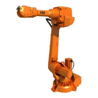
Summarization of Contents
Overview of this manual
About this manual
Provides information about the manual's content, usage, intended audience, and prerequisites.
Usage
Details the scenarios and phases during which this manual should be consulted.
Who should read this manual?
Identifies the target personnel for this product manual.
Prerequisites
Outlines the necessary training and knowledge for personnel working with ABB Robots.
Product manual scope
Defines the range of IRB 2600/IRB 2600 ID variants and designs covered by the manual.
Organization of chapters
Describes the structure and content of the manual's chapters.
References
Lists related ABB documentation and their corresponding Document IDs.
Revisions
Details the changes and updates made in different revisions of the manual.
Product documentation
Categories for user documentation from ABB Robotics
Divides ABB Robotics user documentation into categories like Product manuals, Technical reference manuals, and Application manuals.
Product manuals
Describes the typical content of Product manuals for manipulators and controllers.
Technical reference manuals
Explains the purpose of technical reference manuals for robotics products.
Application manuals
Details the content of application manuals for specific software or hardware options.
Operating manuals
Describes the focus of operating manuals on hands-on handling for production personnel.
How to read the product manual
Reading the procedures
Explains how to interpret references to figures, tools, and materials within procedures.
References to figures
Describes how component references in procedures link to figures.
References to required equipment
Explains how procedure references link to lists of required equipment.
Safety information
Highlights the importance of reading the separate safety chapter and specific safety info within procedures.
Illustrations
Notes that illustrations may be general and not specific to the current robot model.
1 Safety
1.1 General safety information
Covers essential safety aspects and personnel requirements for robot operation.
1.1.1 Limitation of liability
States ABB's limitations of liability regarding robot safety and system integration.
1.1.2 Protective stop and emergency stop
Refers to the controller's product manual for descriptions of protective and emergency stops.
1.2 Safety actions
Details immediate actions to be taken in specific safety-related scenarios.
1.2.1 Fire extinguishing
Recommends using a Carbon Dioxide (CO2) extinguisher for fires involving the robot or controller.
1.2.2 Emergency release of the robot axes
Explains how to manually release robot axis brakes in emergency situations.
1.2.3 Make sure that the main power has been switched off
Emphasizes the lethal danger of high voltage and the necessity to switch off main power.
1.3 Safety risks
Identifies various risks associated with robot installation, service, and operation.
1.3.1 Safety risks during installation and service work on robots
Details risks related to personnel qualifications, general installation hazards, and operational disturbances.
1.3.2 Moving robots are potentially lethal
Warns that moving robots are lethal machines due to unexpected movements and high forces.
1.3.3 First test run may cause injury or damage
Highlights safety risks before the first test run after installation, maintenance, or repair.
1.3.4 Work inside the working range of the robot
Provides critical warnings and safety measures for working within the robot's operational area.
1.3.5 Enabling device and hold-to-run functionality
Explains the function and safe usage of the three-position enabling device and hold-to-run.
1.3.6 Risks associated with live electric parts
Details risks related to high voltage in the controller and manipulator.
1.3.7 The unit is sensitive to ESD
Warns about electrostatic discharge (ESD) sensitivity and provides protective measures.
1.3.8 Hot parts may cause burns
Warns about hot components during operation and the risk of fire from flammable materials.
1.3.9 Safety risks related to pneumatic/hydraulic systems
Addresses general safety regulations, residual energy, and safe design for pneumatic/hydraulic systems.
1.3.10 Safety risks with pressure relief valve
Explains the importance of the pressure relief valve for preventing overpressure.
1.3.11 Brake testing
Describes how to test the holding brake function of each axis motor.
1.3.12 Safety risks during handling of batteries
Details risks associated with battery handling, including exposure and fire/explosion hazards.
1.3.13 Safety risks during work with gearbox lubricants (oil or grease)
Highlights safety risks when handling gearbox lubricants, including heat and allergic reactions.
1.4 Safety signals and symbols
Specifies all safety signals, danger levels, and symbols used in the manuals.
1.4.1 Safety signals in the manual
Defines the captions and significance of danger levels (DANGER, WARNING, CAUTION).
1.4.2 Safety symbols on product labels
Describes safety symbols used on product labels for warnings and prohibitions.
2 Installation and commissioning
2.1 Introduction
Introduces the chapter's content on installing the IRB 2600/IRB 2600 ID at the working site.
2.2 Unpacking
Covers procedures for unpacking and initial pre-installation checks.
2.2.1 Pre-installation procedure
Details pre-installation steps, prerequisites for personnel, and weight specifications.
Loads on foundation, robot
Illustrates stress forces and provides load tables for floor, wall, and suspended mounting.
Requirements, foundation
Specifies requirements for the robot's foundation, including flatness and tilt.
Storage conditions, robot
Defines the allowed ambient temperature and humidity for robot storage.
Operating conditions, robot
Specifies the allowed ambient temperature and humidity for robot operation.
Protection classes, robot
Lists available protection types and their corresponding IP classes for the robot.
2.2.2 Working range and type of motion
Shows robot working ranges and specifies motion types and ranges for each axis.
2.2.3 Risk of tipping/stability
Warns about the risk of tipping if the robot is not properly fastened to the foundation.
2.3 On-site installation
Covers procedures for installing the robot at its designated site.
2.3.1 Lifting robot with roundslings
Provides instructions and required equipment for safely lifting the robot using roundslings.
2.3.2 Lifting and turning a suspended mounted robot
Describes how to lift and turn a robot into a suspended or tilted position using accessories.
2.3.3 Setting the system parameters for a suspended or tilted robot
Explains how to configure system parameters for non-standard robot mounting angles.
2.3.4 Manually releasing the brakes
Details procedures for manually releasing robot axis brakes using push-buttons or external power.
2.3.5 Orienting and securing the robot
Describes how to orient and securely fasten the robot to its foundation or base plate.
2.3.6 Fitting equipment on robot
Covers mounting holes and load areas for fitting additional equipment onto the robot.
2.3.7 Loads fitted to the robot, stopping time and braking distances
Addresses defining loads and their impact on robot stopping time and braking distances.
2.4 Restricting the working range
Explains how to limit the robot's working range using hardware or software.
2.4.1 Axes with restricted working range
Details how to restrict working ranges for specific axes using mechanical stops and software.
2.4.2 Mechanically restricting the working range of axis 1
Describes how to mechanically limit the turning range of axis 1 using stop lugs.
2.5 Installing options
Covers the installation procedures for various optional robot equipment.
2.5.1 Installation of cooling fan for motors (option)
Details the installation procedure for optional cooling fans on motors axis 1 and 2.
2.5.2 Installing an expansion container
Explains the installation of an expansion container for gearbox axis 1 on suspended robots.
2.5.3 Installation of Foundry Plus Cable guard (option no. 908-1)
Refers to separate instructions for installing the Foundry Plus Cable guard.
2.5.4 Signal lamp (option)
Describes the mounting and function of an optional signal lamp as a safety device.
2.6 Robot in hot environments
Provides procedures for starting the robot in hot environments, addressing potential overpressure.
2.7 Robot in cold environments
Describes procedures for starting the robot in cold environments if normal startup fails.
2.8 Electrical connections
Covers robot cabling and connection points for power, signals, and customer equipment.
2.8.1 Robot cabling and connection points
Specifies main cable categories and details robot cable types and connection points.
2.8.2 Customer connection on robot
Details customer connection points on the robot's upper arm and base for external equipment.
2.8.3 Customer connections on upper arm
Shows customer connection points on the upper arm, including signal and power supply connections.
3 Maintenance
3.1 Introduction
Outlines the chapter's scope, covering recommended maintenance activities and procedures.
3.2 Maintenance schedule and expected component life
Provides information on maintenance intervals and expected component lifespans.
3.2.1 Specification of maintenance intervals
Defines how maintenance intervals are specified (calendar time, operating time, SIS).
3.2.2 Maintenance schedule
Details required maintenance activities and intervals for standard and optional equipment.
3.2.3 Expected component life
Provides expected component life based on usage and protection type.
3.3 Inspection activities
Covers inspection procedures for various robot components like gearboxes, cables, and labels.
3.3.1 Inspecting oil level, axis-1 gearbox
Details how to inspect the oil level for the axis-1 gearbox in floor-mounted and suspended robots.
3.3.2 Inspecting the oil level, axis 2 gearbox
Provides instructions for inspecting the oil level in the axis-2 gearbox.
3.3.3 Inspecting the oil level, axis 3 gearbox
Details the procedure for inspecting the oil level in the axis-3 gearbox.
3.3.4 Inspecting the oil level, axis 4 gearbox
Explains how to inspect the oil level in the axis-4 gearbox.
3.3.5 Inspecting oil level, gearbox axes 5 - 6
Describes how to inspect the oil level in the gearbox for axes 5 and 6 (wrist unit).
3.3.6 Inspecting the cable harness
Covers the procedure for inspecting the robot's cable harness for wear or damage.
3.3.7 Inspecting information labels
Details how to inspect the various information labels on the robot.
3.3.8 Inspecting the mechanical stop pin, axis 1
Provides instructions for inspecting the mechanical stop pin on axis 1.
3.3.9 Inspecting additional mechanical stops
Details how to inspect additional mechanical stops fitted to axis 1.
3.3.10 Inspecting dampers
Covers the procedure for inspecting the robot's dampers for damage or impressions.
3.3.11 Inspecting the pressure relief valve
Explains the procedure for inspecting the pressure relief valve's condition.
3.3.12 Inspecting Signal lamp (option)
Describes how to inspect the function of the optional signal lamp.
3.4 Replacement / Changing activities
Covers activities related to changing lubricants and other components.
3.4.1 Type of lubrication in gearboxes
Guides users on where to find information about lubrication types, amounts, and equipment.
3.4.2 Changing the oil, axis 1 gearbox on floor mounted robots
Provides step-by-step instructions for changing the oil in axis-1 gearbox for floor-mounted robots.
3.4.3 Changing the oil, axis-1 gearbox on suspended robots
Details the procedure for changing axis-1 gearbox oil on suspended robots.
3.4.4 Changing the oil, axis-2 gearbox
Provides instructions for draining and filling oil in the axis-2 gearbox.
3.4.5 Changing the oil, axis-3 gearbox
Covers the procedure for draining and refilling oil in the axis-3 gearbox.
3.4.6 Changing the oil, axis-4 gearbox
Details the steps for draining and filling oil in the axis-4 gearbox.
3.4.7 Changing oil, axes-5 and -6 gearboxes
Provides procedures for draining and filling oil in the axes 5 and 6 gearboxes (wrist unit).
3.4.8 Replacing SMB battery
Guides on replacing the SMB battery, including alerts and battery lifetime information.
3.5 Cleaning
Covers general cleaning procedures and special considerations for the robot.
3.5.1 Cleaning the IRB 2600/IRB 2600 ID
Provides information on cleaning methods based on robot protection types and special considerations.
4 Repair
4.1 Introduction
Introduces the chapter on repair activities for the IRB 2600/IRB 2600 ID and external units.
4.2 General procedures
Covers general procedures applicable to various repair tasks.
4.2.1 Performing a leak-down test
Details the procedure for testing the integrity of gearbox seals after refitting.
4.2.2 Mounting instructions for bearings
Provides instructions on how to mount and grease different types of bearings on the robot.
4.2.3 Mounting instructions for seals
Describes how to mount rotating, flange, static seals, and O-rings.
4.2.4 Cut the paint or surface on the robot before replacing parts
Explains the procedure for cutting paint or surface before replacing parts to avoid cracks.
4.2.5 The brake release buttons may be jammed after service work
Addresses potential jamming of brake release buttons after SMB recess service work.
4.3 Complete robot
Covers procedures for removing and refitting complete robot components like cable harnesses.
4.3.1 Removing the complete cable harness
Details the procedure for removing the complete cable harness from the robot's base, frame, and lower arm.
4.3.2 Refitting the complete cable harness
Provides step-by-step instructions for refitting the robot's cable harness.
4.3.3 Replacing the cable harness in the upper arm - IRB 2600ID
Details the procedure for replacing the cable harness specifically in the upper arm of IRB 2600ID.
4.3.4 Replacing SMB unit
Covers the procedure for removing and refitting the SMB unit.
4.3.5 Replacing the brake release board
Provides instructions for removing and refitting the brake release board.
4.4 Upper arm
Covers procedures related to the upper arm component of the robot.
4.4.1 Replacing the complete upper arm
Details the procedure for replacing the entire upper arm assembly.
4.4.2 Replacing complete tubular shaft unit
Describes how to replace the complete tubular shaft unit (not valid for IRB 2600ID).
4.4.3 Replacing wrist unit
Provides instructions for replacing the wrist unit on IRB 2600 Standard and IRB 2600ID.
4.4.4 Measuring the play, axis 5
Details the procedure for measuring play in axis 5 for IRB 2600.
4.4.5 Measuring the play, axis 6
Describes the procedure for measuring play in axis 6 for IRB 2600.
4.4.6 Measuring the play, axis 5 (ID upper arm)
Details the procedure for measuring play in axis 5 for IRB 2600ID upper arm.
4.4.7 Measuring the play, axis 6 (ID upper arm)
Describes the procedure for measuring play in axis 6 for IRB 2600ID upper arm.
4.5 Lower arm
Covers procedures related to the lower arm component of the robot.
4.5.1 Replacing the lower arm
Provides instructions for removing and refitting the lower arm.
4.6 Frame and base
Covers procedures related to the robot's frame and base.
4.6.1 Replacing stop pin axis 1
Details the procedure for replacing the stop pin on axis 1.
4.6.2 Replacing the base
Provides instructions for removing and refitting the robot's base.
4.7 Motors
Covers procedures related to robot motors, including removal and refitting.
4.7.1 Removing motors
Details the procedure for removing motors from all robot axes.
4.7.2 Refitting motors
Provides instructions for refitting motors on all robot axes, including filling oil and torque specifications.
4.7.3 Replacing motor axis 5 - IRB 2600ID
Covers the procedure for replacing the motor on axis 5 for IRB 2600ID.
4.7.4 Replacing motor axis 6 and wrist unit - IRB 2600ID
Details the procedure for replacing the axis-6 motor and wrist unit on IRB 2600ID.
4.7.5 Adjusting the play
Explains how to adjust play in the robot motors.
4.8 Gearboxes
Covers procedures related to replacing robot gearboxes.
4.8.1 Replacing gearbox axis 1
Provides instructions for replacing the gearbox on axis 1, including different versions.
4.8.2 Replacing gearbox axis 2
Details the procedure for replacing the gearbox on axis 2, including different versions.
4.8.3 Replacing gearbox axis 3
Covers the procedure for replacing the gearbox on axis 3.
5 Calibration
5.1 Introduction to calibration
Provides general information and terminology related to robot calibration.
5.1.1 Introduction and calibration terminology
Defines key terms and concepts used in robot calibration procedures.
5.1.2 Calibration methods
Specifies the different types of calibration methods supplied by ABB.
5.1.3 When to calibrate
Outlines the situations that require robot system calibration.
5.2 Synchronization marks and axis movement directions
Shows synchronization marks and defines movement directions for robot calibration.
5.2.1 Synchronization marks and synchronization position for axes
Illustrates synchronization marks for IRB 2600 and IRB 2600ID models.
5.2.2 Calibration movement directions for all axes
Provides diagrams showing manual movement directions for robot calibration.
5.3 Updating revolution counters
Describes how to perform rough calibration by updating revolution counters via FlexPendant.
5.4 Calibrating with Axis Calibration method
Covers the standard and most accurate calibration method for IRB 2600/IRB 2600 ID.
5.4.1 Description of Axis Calibration
Explains the Axis Calibration procedure, tools, and safety warnings.
5.4.2 Calibration tools for Axis Calibration
Details the calibration tool set, its requirements, and how to examine it.
5.4.3 Installation locations for the calibration tools
Shows where calibration tools are installed on the robot's axes.
5.4.4 Axis Calibration - Running the calibration procedure
Provides an overview and steps for running the Axis Calibration procedure on the FlexPendant.
5.5 Calibrating with Calibration Pendulum method
Directs users to documentation for the Calibration Pendulum method.
5.6 Verifying the calibration
Describes how to verify the robot's calibration results after the process.
5.7 Checking the synchronization position
Explains how to check the robot's synchronization position using MoveAbsJ or Jogging.
6 Decommissioning
6.1 Introduction
Provides information on taking products, robots, or controllers out of operation.
6.2 Environmental information
Details disposal regulations, hazardous materials, and oil/grease handling.
6.3 Scrapping of robot
Highlights important safety precautions to prevent injuries during robot disassembly.
7 Robot description
7.1 Robot types
Describes different variants of IRB 2600 (Type A, B, C) and their motor/gearbox differences.
7.2 Non-compatible versions of axis-1 and axis-2 gearboxes
Explains non-compatibility of axis-1 and axis-2 gearboxes from different suppliers.
8 Reference information
8.1 Introduction
Introduces the chapter containing general information complementing specific procedures.
8.2 Applicable standards
Lists applicable EN ISO, European, and other standards relevant to robot design and safety.
8.3 Unit conversion
Provides a converter table for units used throughout the manual.
8.4 Screw joints
Describes how to tighten various screw joints, including UNBRAKO, Gleitmo, and lubricated screws.
8.5 Weight specifications
Provides component weights and recommends lifting accessories for items exceeding 22 kg.
8.6 Standard tools
Lists standard tools required for service, repair, and installation procedures.
8.7 Special tools
Lists special tools required for specific service procedures, including measuring and calibration equipment.
8.8 Lifting accessories and lifting instructions
States that lifting accessories are specified in procedures and their instructions should be stored.
9 Spare part lists
9.1 Spare part lists and illustrations
Indicates that spare parts and exploded views are available separately on the myABB Business Portal.
10 Circuit diagram
10.1 Circuit diagrams
States that circuit diagrams are available for registered users on the myABB Business Portal.
Need help?
Do you have a question about the IRB 2600ID-15/1.85 and is the answer not in the manual?
Questions and answers