Table of Contents
Advertisement
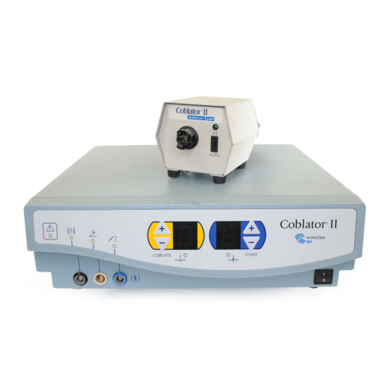
COBLATOR
®
II (RF80000E) SYSTEM
3
User's Manual
This equipment has been tested and found to comply with the limits for medical devices to IEC/EN 60601-1-2:2007.
These limits are designed to provide reasonable protection against harmful interference in a typical medical
installation. This equipment generates, uses, and can radiate radiofrequency energy and, if not installed and used
in accordance with the instructions, may cause harmful interference to other devices in the vicinity. If this equipment
does cause harmful interference to other devices, which can be verified by turning the equipment off and on, the
user is encouraged to try to correct the interference by one or more of the following measures:
High frequency surgical unit with respect to electrical shock, fire and mechanical hazards only in accordance with:
UL 60601-1/CAN/CSA C22.2 No. 601.1, IEC/EN 60601-2-2.
Advertisement
Table of Contents

Related Manuals for ArthroCare RF8000E


Summarization of Contents
Description, Indications, and Contraindications
Description
Details the components and function of the electrosurgical system.
Indications for Use
Specifies the surgical procedures for which the system is intended.
Contraindications
Lists conditions or situations where the system should not be used.
System Overview
Connection Diagram
Visual representation of how system components connect to each other.
Principle of Operation
Principle of Operation
Explains the electrosurgical process and energy delivery mechanism.
Warnings, Precautions, and Adverse Events
WARNINGS
Critical safety warnings for potential hazards during system operation.
PRECAUTIONS
Recommended safety measures to prevent injury or equipment damage.
Controls, Indicators, and Alarms
Controls & Indicators
Description of system controls, visual indicators, and their functions.
Alarms
Explanation of audible alarms and their corresponding error conditions.
Diagram of Controls, Indicators, and Alarms
Diagram of Controls, Indicators, and Alarms
Visual layout of the controller's front and rear panels with numbered components.
Unpacking, Assembly, and System Check
Unpacking
Instructions for verifying received equipment and handling potential damage.
Assembly and System Check
Steps for connecting components and performing an initial system test.
Instructions for Use
Operator Training Requirements
Specifies the necessary training and experience for system operators.
General System Operation
Basic operational procedures and activation methods using the foot control.
Voltage Outputs
Voltage Outputs
Details the output voltage levels for Coblate and Coagulation modes based on set points.
System Preparation and Care
System Preparation
Procedures for preparing the system, including connections and fluid setup.
Wand Selection
Wand Selection
Guidance on choosing the appropriate Wand type for specific procedures.
System Shut Down
System Shut Down
Step-by-step instructions for safely powering off and disconnecting the system.
System Storage and Transport
System Storage and Transport
Guidelines for proper storage conditions and transportation of the system.
Equipment Disposal
Equipment Disposal
Instructions for the environmentally responsible disposal of electronic components.
Cleaning and Disinfection
Controller, Flow Control Valve Unit, and Flow Control Cable
Cleaning procedures for the main controller and associated fluid components.
Foot Control
Recommended methods for cleaning and disinfecting the foot control unit.
Wand
Information on Wand cleaning, reuse restrictions, and sterility.
Maintenance and Troubleshooting
Maintenance
Overview of maintenance requirements and user-serviceable parts.
Fuse Replacement
Detailed instructions for safely replacing fuses in the controller.
Troubleshooting Guide
Guidance for identifying and resolving common system operational issues.
Product Specifications
Technical Specifications
Detailed technical parameters including power, dimensions, and operating conditions.
Controller Output Graphs
Controller Output Graphs
Graphs illustrating output power versus set point for Coblate and Coagulation modes.
Output Power vs. Load Resistance
Output Power vs. Load Resistance, Coblate
Graph showing Coblate output power at different load resistances.
Output Power vs. Load Resistance, Coagulation
Graph showing Coagulation output power at different load resistances.
Open Circuit Voltage Measurements
Open Circuit Voltage Measurements, Coblate
Graph showing Coblate open circuit voltage at different set points.
Open Circuit Voltage Measurements, Coagulation
Graph showing Coagulation open circuit voltage at different set points.
Electromagnetic Environment Specifications
Electromagnetic Emissions
Details RF emissions and guidance for the electromagnetic environment.
Electromagnetic Immunity
Electromagnetic Immunity
Details immunity test levels, compliance, and guidance for electromagnetic fields.
Controller Classification and Safety Verification
Classification
Classification of the controller based on electrical shock protection and water ingress.
Safety Verification
Verification of leakage current levels according to international safety standards.
Customer Service
Warranty Information
Details the warranty period and coverage for the system components.
Product Complaints
Instructions on how to direct questions or concerns regarding product quality.
Symbols Key
Symbols Key
Explanation of the various symbols used throughout the user manual.
Need help?
Do you have a question about the RF8000E and is the answer not in the manual?
Questions and answers