Table of Contents
Advertisement
Quick Links
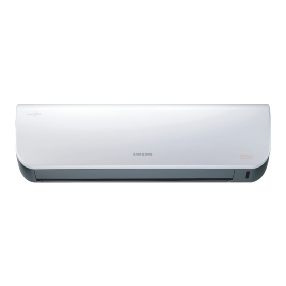
AIR CONDITIONER
AQV09AAN, AQV12AAN
AQV09AAX, AQV12AAX
Refer to the service manual in the GSPN(see the rear cover) for the more information.
SPLIT-TYPE AIR CONDITIONER
INDOOR UNIT
Basic : AQV09VBA
AQV12VBA
Model : AQV09AA Series
AQV12AA Series
Model Code : AQV09AAN
AQV12AAN
CONTENTS
1. Precautions
2. Product Specifications
3. Disassembly and Reassembly
4. Troubleshooting
5. Exploded Views and Parts List
6. PCB Diagram and Parts List
7. Wiring Diagram
8. Schematic Diagram
9. Reference Sheet
OUTDOOR UNIT
AQV09AAX
AQV12AAX
Advertisement
Table of Contents

Summarization of Contents
Precautions for Safe Operation
Service Precautions
Guidelines for safe and proper servicing of electric parts and assembly.
Static Electricity and PL Precautions
Warnings regarding static electricity and personal limitations for repair.
General Safety Precautions
Safety measures for electrical hazards, cord handling, and product usage.
Product Features and Design
Key Product Features Explained
Detailed explanation of BLDC, Half Mirror Design, good'sleep, mpiZone, and Silence Mode.
Design and Component Updates
Compares design changes and new components with basic models.
New Component Applications
Details new components like MPI LAMP, DNA filter, Grille door, and Cross flow fan.
Display Indicator Guide
Explains the function of display indicators for various operating modes.
Comparative Product Specifications
Model Specification Comparison Table
Table detailing technical specifications for different models (Capacity, Noise, Power, etc.).
Accessories and Optional Parts
Included Accessories List
Lists all accessories included with the unit, with part numbers and descriptions.
Air Filters Information
Details the types of filters, their codes, and maintenance instructions.
Troubleshooting and Error Resolution
Remote Control Option Setup Procedure
Step-by-step guide for entering and setting option codes via the remote control.
Error Code Diagnosis and Verification
Lists error codes, their causes, and troubleshooting steps for unit malfunctions.
Symptom-Based Fault Diagnosis
Procedures for diagnosing faults based on specific symptoms and error indicators.
PCB Inspection and Troubleshooting
PCB Pre-Inspection Guidelines
Important notices before inspecting PCBs, like unplugging power and handling safety.
PCB Inspection Process
General steps for inspecting PCBs, including checking connections and components.
Indoor PCB Detailed Checks
Specific checks and methods for diagnosing indoor unit PCBs.
Outdoor PCB Detailed Checks
Specific checks and methods for diagnosing outdoor unit PCBs.
Key Component Inspection
Room Temperature Sensor Check
Method for measuring resistance of the room temperature sensor for normal/abnormal states.
Room Fan Motor Resistance Check
Procedure to measure room fan motor resistance between terminals for normal/abnormal states.
Stepping Motor Resistance Check
How to measure stepping motor resistance between wires for normal/abnormal states.
Exploded Views and Parts Identification
Indoor Unit Exploded Diagram
Exploded view illustration of the indoor unit with numbered parts.
Outdoor Unit Exploded Diagram
Exploded view illustration of the outdoor unit with numbered parts.
PCB Schematics and Component Identification
Indoor Main PCB Block Diagram
Block diagram of the indoor unit's main PCB showing connections and modules.
Indoor Module PCB Diagram
Diagram and connection details for the indoor module PCB.
Indoor Display PCB Diagram
Diagram and connection details for the indoor display PCB.
Outdoor Main PCB Diagram
Diagram of the outdoor unit's main PCB with component and wire connections.
Outdoor EMI PCB Diagram
Diagram of the outdoor unit's EMI PCB, showing power input and filter components.
Main PCB Electrical Component List
Detailed list of electrical components for the main PCB, including codes and specifications.
System Wiring Diagrams
Indoor and Outdoor Unit Wiring
Comprehensive wiring diagram showing connections between indoor and outdoor units.
Electronic Circuit Schematics
Indoor Unit PCB Circuit Overview
Description of PCB circuit blocks and their functions for the indoor unit.
Indoor Unit Schematic Diagram
Detailed schematic of the indoor unit's main PCB circuits.
Indoor Unit Display Circuit Schematic
Schematic for the indoor unit's display and remote control interface circuits.
Outdoor Unit Schematic Diagrams
Overview of schematic modules for the outdoor unit's main components.
Outdoor Unit EMI Circuit Schematic
Schematic for the outdoor unit's EMI (Electromagnetic Interference) filter circuit.
Reference Information
Refrigeration Cycle Diagram
Diagram illustrating the refrigerant flow for cooling and heating modes.
Model Name Coding System
Explanation of the model code structure and its components.
Refrigerant Pressure Charts
Charts showing refrigerant pressure distribution based on temperature.


Need help?
Do you have a question about the AQV12A Series and is the answer not in the manual?
Questions and answers