Table of Contents
Advertisement
Q7055C Building Network Adapters
BNA-1C/2CS
WARNING
This equipment generates, uses and can radiate
radio frequency energy, and if not installed and
used in accordance with the Instructions Manual,
may cause interference with radio communication.
It has been tested and found to comply with the
limits for a Class A computing device pursuant to
Subpart J of Part 15 or FCC Rules, which are
designed to provide reasonable protection against
such interference when operated in a commercial
environment. Operation of this equipment in a
residential area is likely to cause interference, in
which case, users at their own expense will be
required to take whatever measures may be
required to correct the interference. Any
unauthorized modification of this equipment may
result in the revocation of the owner's authority to
continue its operation.
GENERAL
The Q7055C series Building Network Adapters (BNA) provide
®
connection of a Honeywell
an industry standard 10/100BaseT Ethernet LAN. The
Building Network Adapter (BNA) delivers exceptional price/
performance to meet the requirements of both building owners
and service providers. With its combination of scalable
performance, density, and low per-port pricing, the BNA
allows network-layer capabilities to be extended to a much
wider range of network configurations and environments.
High-performance network and services, including traffic
management, are now available to additional locations
throughout the network.
The BNA uses the LAN-connection to provide a seamless
communication to the requesting device. Status information
such as LAN communication activity, field bus traffic
communication, and system Heartbeat of the BNA is indicated
by LEDs on the front of the device.
The BNA models provide an interface from various Honeywell
controller buses that use RS-485 signals to a local area
network using 802.3 Ethernet protocol. This allows data to be
used by high-level Building Management Systems such as the
Honeywell Enterprise Buildings Integrator (EBI)
This Installation Instruction covers the following BNA devices:
controller communication bus to
™
.
INSTALLATION INSTRUCTIONS
— Q7055C1009 BNA-1C. Provides a single RS-485 DC
coupled C-Bus-compatible communication channel for
®
Excel 5000
family devices with up to 76.8 kbps.
— Q7055C1017 BNA-2CS. Provides two RS-485 DC
coupled C-/S-Bus compatible communication chan-
nels for Excel Classic and XL5000 family devices in
smoke control systems with up to 76.8 kbps.
Additionally, each BNA is equipped with a RJ-45 10/100BaseT
connector, plus an RS-232 interface. (see Fig. 1).
WORKSTATION
LOCAL AREA NETWORK
BNA-1C
SINGLE C-BUS
(ONLY FOR XL5000, IRC AND EMC
CONTROLLERS FAMILIES)
EMC, EXCEL CLASSIC
CONTROLLERS FAMILIES)
Fig. 1. BNA network.
The Q7055C Building Network Adapter is used in systems for
signaling smoke control of fire (UL 864-9th), UL 916, and
general purpose signaling (UL 2017). Also applies to CEC
22.1 standard. In UL 2017 applications, the product can be
used as either a type SM (Self-Monitored) or type AM
(Attendant-Monitored) system.
SPECIFICATIONS
Models:
Q7055C1009 Building Network Adapter BNA-1C. Provides a
single RS-485 DC coupled C-Bus-compatible
communication channel for XL800 and Excel 5000 family
devices with up to 76.8 kbps.
EBI
WORKSTATION
ETHERNET
BNA-2CS
TWO C-/S-BUS
(FOR EXCEL IRC,
AND XL5000
M25320
95-7735
Advertisement
Table of Contents

Related Manuals for Honeywell Q7055C1017 BNA-2C


Summarization of Contents
Location and Mounting
Single Device Mounting
Shows the single BNA device operating position, for example, on a desk.
Stacked Devices Mounting
BNA devices may also be stacked, but not recommended for smoke control applications.
Wall Mounting
Describes how the device should be prepared prior to mounting it on a wall.
Communications Panel Mounting
Mounting the BNA device in the 14006090-555151 series Communications Panel.
Connections
Power Connection
Details the requirements for connecting the BNA device to a power supply.
Field Bus Connection
Explains how to connect the field bus to the BNA device using Phoenix connectors.
Cables and Connectors
DB9F Null Modem Connector
Illustrates a serial connector and shows how to configure a Null Modem Cable DB9F.
RJ-45 LAN Connector
Describes the pin layout for the RJ-45 connector used for 10/100BaseT Ethernet LAN.
Ethernet Connection
Connect BNA to HUB
Details the cable configuration for connecting a BNA device to a LAN via an Ethernet Hub.
Connect BNA to Workstation
Explains the need for a crossover cable for direct workstation connection.
Operation
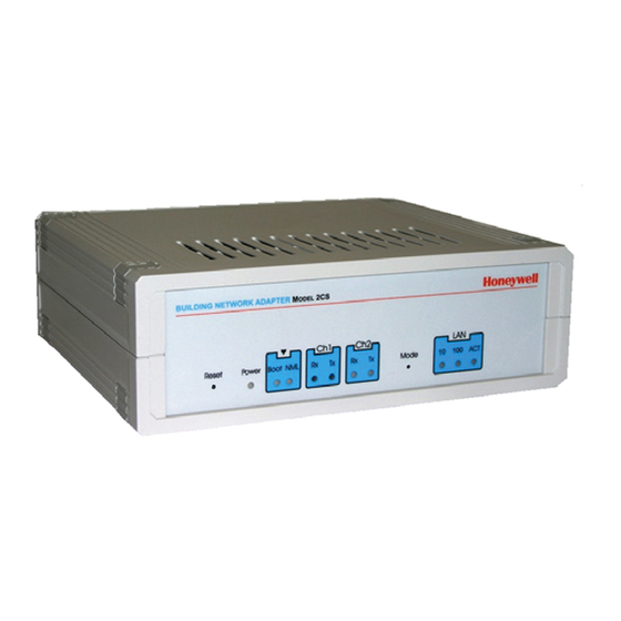
Location of Parts and Controls
Identifies and describes the functions of parts and controls on the front and rear of the BNA.
LED Indicators
Explains the meaning of the various LEDs on the BNA device for status indication.
Bus Channel Connectors
Details the 2-pin connectors for field bus channel 1 and channel 2 connections.
Bus Termination Switches
Describes the switches used to select field bus termination and biasing.
Power Input
Specifies the power connector for 24 VAC or 24 VDC supplies and chassis ground.
RS-232 Interface
Details the 9-pin SUB-D male RS-232 connector for initial device setup.
Need help?
Do you have a question about the Q7055C1017 BNA-2C and is the answer not in the manual?
Questions and answers