Table of Contents
Advertisement
Advertisement
Table of Contents

Related Manuals for DOD Technologies CL1


Summary of Contents for DOD Technologies CL1
- Page 1 ChemLogic 1 & 2 ® Continuous Gas Monitor User Manual...
- Page 2 CL1 & CL2 Manual © DOD Technologies, INC 675 Industrial Drive Bldg. A. Cary, IL 60013 Phone 815.788.5200 • Fax 815.788.5300 DC-ITD-CL1andCL2MAN01-2018.A www.dodtec.com NOV 2018 815-788-5200...
- Page 3 105 route des pommiers Centre Ubidoca 74370 St Martin Bellevue France DOD TECHNOLOGIES INC. declares under our sole responsibility that the product described as: Equipment Name: Continuous Gas Monitor Equipment Description: Detection and measurement of toxic gases Model: CL1/CL2 Serial number(s): _______________ Complies with the requirements of the following European Directives: Machinery Directive 2006/42/EC;...
-
Page 4: Table Of Contents
CL1 & CL2 Manual Table of Contents Chapter 1 – Overview ..................................7 1.1 Introduction ................................... 7 1.2 Sampling and Monitoring ..............................7 1.3 Flow Connections ................................. 7 1.4 Electrical Connections ................................8 1.5 Theory of Operation ................................8 Chapter 2 – Features ..................................9 2.1 External Layout .................................. - Page 5 CL1 & CL2 Manual 5.5.4 Gate & Tape ..................................23 5.5.5 Alarm Levels ..................................23 5.5.6 Event & Alarm History ..............................23 5.5.7 Test Alarms ..................................23 5.6 Setup Menu ..................................24 5.6.1 Main Menu ..................................24 5.6.2 Tape Saver ..................................24 5.6.3 Latching Relays ................................
- Page 6 CL1 & CL2 Manual F.1 Concentration Log Files ..............................48 F.2 Event Log Files ..................................48 F.3 Formatting Micro SD Disks ..............................49 F.3 SD Card Status Menu Item ..............................51 Appendix G – ChemLogic ® Cassettes ............................52 Appendix H – Advanced Optics Cleaning Procedure ........................ 53 H.1 Optic Orifice Cleaning ................................
-
Page 7: Chapter 1 - Overview
1 & 2 continuous gas detection system without a manual in the native language in its country of operation is illegal. A translated copy of the manual should be requested immediately from DOD Technologies and before installation of the device. Failure to do so may result in severe injury. Contact: Phone: +1 815-788-5200 email: solutions@dodtec.com... -
Page 8: Electrical Connections
CL1 & CL2 Manual 1.4 Electrical Connections The unit is powered with a standard AC Power plug. A single 14 pin connector on the side of the CL1/CL2 provides all electrical connections for the outputs and remote reset. NOTE: Maximum Branch-Circuit Rating = 20 Amperes 1.5 Theory of Operation The sample flow is diverted across the ChemLogic ®... -
Page 9: Chapter 2 - Features
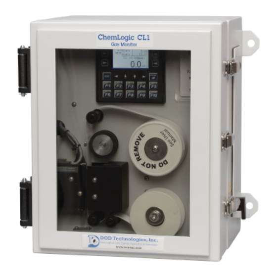
CL1 & CL2 Manual Chapter 2 – Features 2.1 External Layout Maintenance Door Keypad & Display Exhaust Outlet Take-up reel 14 pin I/O Connector Door latches (side of unit) A/C Power & ChemLogic® Tape Switch Gas tubing inlet (underside) Figure. 2.1 2.1.1 Warning Labels, Descriptions, &... -
Page 10: Chemlogic ® 1 & 2 Danger Zones
CL1 & CL2 Manual WARNING: Electric Shock is possible, please use caution when accessing this zone. WARNING: Moving Parts and Hand Crushing possible. Please watch hand placement when working near this zone. 2.1.2 ChemLogic ® 1 & 2 Danger Zones ®... -
Page 11: Keypad & Display
CL1 & CL2 Manual IMPORTANT: The maintenance door should remain closed and latched except when changing the ChemLogic ® tape. 2.1.4 Keypad & Display The CL1/CL2 uses a two-color LCD display with a 20-button keypad including 4 programmable “soft keys”. See chapter 5 for a complete description on the use of the keypad and display. -
Page 12: Internal Layout - Service Area
2.4 Micro Secure Digital Card (SD Card) The CL1/CL2 uses a SD card to store historical information including concentration logging, event history, configuration information, and TWA data. SD cards may be purchased through DOD Technologies – see Appendix A. DC-ITD-CL1andCL2MAN01-2018.A www.dodtec.com... -
Page 13: Chapter 3 - Installation
The CL1/CL2 requires stable temperature and humidity levels within range to operate properly (see Appendix C) NOTE: Options are available for heating or cooling the CL1/CL2 – Contact DOD Technologies for details. RECOMMENDATIONS: Do not place in a location which will expose the CL1/CL2 to moisture, dust, corrosive gas, or any unusual environmental conditions which could damage the unit and/or cause it to operate inaccurately. -
Page 14: Mounting
CL1 & CL2 Manual Get as close to the load as possible • Walk over to the load – don’t stand still and reach for it Maintain the normal curves in your spine You need to try and work in your power zone – above your knees and below the shoulders •... -
Page 15: Sample Tubing
An end of line particulate filter must be used on all gasses except Diisocyanates to prevent loss of concentration. Filters require regular maintenance – see chapter 6. End of line particulate filters may be purchased from DOD technologies (see appendix A) IMPORTANT: The CL1/CL2 requires filtration to prevent dust accumulation in tubing and internal damage to the unit. - Page 16 CL1 & CL2 Manual DANGER: Turn off the unit, disconnect A/C power and unplug the 14 pin I/O connector on the side of the unit (if installed) before any wiring modifications. DC-ITD-CL1andCL2MAN01-2018.A www.dodtec.com NOV 2018 815-788-5200...
-
Page 17: Chapter 4 - Setup & Configuration
CL1 & CL2 Manual Chapter 4 – Setup & Configuration 4.1 User Checklist Follow this checklist to configure the CL1/CL2 for first time operation or after a software upgrade. ___ Set passwords (section 5.6.3) ___ Set system date and time (section 5.5.7) ___ Gas selection (section 5.5.9) Appendix E contains the specifications for each gas. -
Page 18: Chapter 5 - Basic Operation
CL1 & CL2 Manual Chapter 5 – Basic Operation 5.1 Using the Keypad The CL1/CL2 is controlled using the keypad located around the display. All the display screens are accessed through a simple menu system. Note 2 Note 1 Note 3 NOTE 1) The arrow keys located under the screen are used for two purposes. - Page 19 CL1 & CL2 Manual See Appendix D for a description of each message. The history log always keeps the most recent 128 messages of any type in memory. All three types of messages are also logged to the Micro SD card if present.
-
Page 20: Menu Overview Cl1/Cl2
CL1 & CL2 Manual 5.3 Menu Overview CL1/Cl2 Setup Menu (5.5) See Note 1 Setup Mode Main Menu (return Auto Analysis Timer Tape Saver Latching Relays Enable Pumps Main Menu (5.4) Enable Points Main Menu Alarm Relays Start Analysis Voltage Cal Idle Timeout System Faults Optic Calib. -
Page 21: Main Menu
CL1 & CL2 Manual 5.5 Main Menu Once the CL1/CL2 is configured the main menu contains all the screens necessary for normal operation. The main menu is not password protected. Figure 5.6 Each selection on the main menu is detailed below 5.5.1 Start Analysis Selecting this menu item will bring up the analysis screen below and start gas analysis. -
Page 22: System Faults
CL1 & CL2 Manual The bar graph on the right side of the display reflects the % of full scale for the current concentration reading. At the lower left of the screen the display will show ‘P1’ or ‘P2’ if a pump is disabled either manually or automatically. -
Page 23: Gate & Tape
CL1 & CL2 Manual 5.5.4 Gate & Tape Touch the lower left <GATE> soft key to open or close the gate. When a new ChemLogic tape is loaded press the <RESET> soft key to reset the counter for a new tape. The tape windows remaining displays the number of tape advances expected before the tape is empty. -
Page 24: Setup Menu
CL1 & CL2 Manual 5.6 Setup Menu The Setup Menu contains the screens necessary to configure the CL1/CL2 for operation. The setup menu is not password protected by default but may be password protected (see service menu). Figure 5.14 Each selection on the setup menu is detailed below 5.6.1 Main Menu Selecting this menu item will return to the main menu (Section 5.4) 5.6.2 Tape Saver... -
Page 25: Latching Relays
CL1 & CL2 Manual In Continuous mode both the time (minutes) and the conc. Level are used. If the concentration should reach the level specified, the timer will start and count down from the time specified to zero before advancing the tape. -
Page 26: Enable Pumps
CL1 & CL2 Manual 5.6.4 Enable Pumps (Default Configuration: Enabled) Press the upper soft keys to toggle between enabled/disabled on the corresponding pump. The display adjacent to the soft key always displays the current state of the pump. (ex: in figure 5.18 both pumps are currently enabled). -
Page 27: Date And Time
CL1 & CL2 Manual 5.6.8 Date and Time Use the arrow keys below the screen to select among the date & time fields and enter the values using the procedure outlined in section 5.1.3. The <SET> soft key must be pressed to apply the changes that are entered. -
Page 28: Service Menu
CL1 & CL2 Manual 5.7 Service Menu The Service menu is intended for client use but should remain password protected to prevent unauthorized access. The default Service Menu password is included with this manual. The password can be changed as needed (see section 5.6.3) 5.7.1 Voltage Cal This menu item is for Factory or Service personnel use, under normal conditions this screen is not used. -
Page 29: Clear History
CL1 & CL2 Manual 5.7.6 Clear History The history screen contains the 128 most recent event, fault, and alarm messages. Each of the messages logs the date/time occurred and the date/time cleared as separate entries. In the “Event/Alarm History” on the Main Menu (Section 5.4.6) it is not possible to clear the history. -
Page 30: Chapter 6 - Maintenance
Please contact DOD Technologies for the safe return of your equipment. All discontinued units will be accepted back by DOD Technologies so proper recycling may take place. For information on how to return the unit contact us using the below information: 6.1 Maintenance Door Access... -
Page 31: Chemlogic ® Paper Tape
CL1 & CL2 Manual Before opening the service, door make sure the maintenance door is securely latched and power is removed. The service door safety lock must be removed with a 3/32” Allen wrench before the service door can be opened. - Page 32 CL1 & CL2 Manual Remove the top tape sleeve with the tape spooled around it by gently pulling away from the machine. Remove the old tape reel from the bottom spindle by lifting over the washer. Discard the old tape & cassette appropriately Remove the new tape reel from the protective packaging.
-
Page 33: End-Of-Line Particulate Filters
CL1 & CL2 Manual On the screen touch the ‘Reset’ soft key. (See section 5.5.4) WARNING: Keep fingers clear during tape advance. 6.4 End-of-Line Particulate Filters End of line (point of detection) particulate filters which protect the CL1/CL2 from damage are required for most gases. -
Page 34: Flow Adjustment
CL1 & CL2 Manual 6.5 Flow Adjustment The pumps in the CL1/CL2 automatically adjust to keep a constant flow to the system. No manual adjustment is necessary. Typical inlet flow rate should read between 700 – 1000 cc’s per minute. 6.6 Micro Secure Digital (SD) Card Replacement See Appendix F for detailed information on the contents of the SD Card. -
Page 35: Grease Application
CL1 & CL2 Manual 6.8 Grease Application The cam attached to the gate motor should be greased every 6 months to prevent wear. Apply a small amount of number 2 type petroleum or synthetic grease to the rounded portion of the cam. – See Figures 6.5 below: Top of gate mechanism Bottom of gate mechanism... -
Page 36: Chapter 7 - Service & Support
CL1 & CL2 Manual Chapter 7 – Service & Support For information on service and support for your CL1/CL2 contact DOD Technologies, INC. using the information below. Phone Support M-F 8am – 5pm (Central Time Zone) 815.788.5200 Service Center 675 Industrial Drive Bldg. A. -
Page 37: Appendix A - Accessories & Spare Parts
CL1 & CL2 Manual Appendix A – Accessories & Spare Parts ChemLogic 2 Month Cassettes 1-200-020 Phosgene ChemLogic 60 Day Cassette $128.00 1-300-020 Hydrides ChemLogic 60 Day Cassette $128.00 1-300-022 Carbonyl Sulfide ChemLogic 60 Day Cassette $128.00 1-400-020 Mineral Acids ChemLogic 60 Day Cassette $128.00 1-490-020 Acetic Acid ChemLogic CL1 60 Day Tape... - Page 38 CL1 & CL2 Manual 2-600-213 CL1 Light Extension Cable w/connectors - up to 100' - Specify Length $180.00 2-600-214 Outdoor Rain Resistant End of Line Cone $55.00 2-600-216 Option CL1 Split Sampling System $350.00 2-600-218 Option CL1 Ethernet IP $1,100.00 2-600-220 CL1 Explosion Safe (Zone 2) Light Tower Option Top Mount $1,325.00...
- Page 39 CL1 & CL2 Manual 2-100-A25 CL1 (ONLY) Optic Block Assembly $820.00 2-100-A26 Assy Micro Switch Field Upgrade $55.00 2-100-A27 Transducer Assembly w/ Wires $50.00 2-100-A34 Assembly Tee Fitting with Double O-rings and with 2 Collets Removed $12.00 2-100-A35 Assy CL1 Exhaust Fitting $9.00 2-100-A36 Assembly - CL1 Upper Fittings &...
-
Page 40: Appendix B - I/O Connection Detail
CL1 & CL2 Manual Appendix B – I/O Connection Detail 14-Pin Cl1/Cl2 I/O Connector Figure B.1 Description Usage System Fault Normally Open System Fault Common System Fault Normally Closed Gas - Alarm Level 1 Normally Closed External Fault Alarm Reset Momentarily connect to pin N for reset Gas - Alarm Level 1 Common... -
Page 41: Appendix C - Technical Specifications
CL1 & CL2 Manual Appendix C – Technical Specifications Physical Dimensions Height 12.5 “ (31.75 cm) Width 10.25” (26.04 cm) Depth 9” (22.86 cm)) Weight 30 lbs. (13.5 kg) Operating Temperature 5 to 40 Degrees Celsius Flow FEP ¼” OD x 1/8” ID (150 ft Max) Sample Tubing Diisocyanates–... -
Page 42: Appendix D - System Event Messages
Event Status Update CL1/C Message Possible Cause Corrective Action Code Contact DOD Technologies Support @ (815) No Gas Data Loaded System Restored 788-5200 See manual appendix H for cleaning instructions. Add filter to inlet if possible. Also, DAC Calibration Optics Dirty... - Page 43 CL1 & CL2 Manual When blockage is fixed, go to Setup Menu and Flow Fluctuation Flow Blocked and/or enable pumps. If problem persists, contact Fault Unstable Inlet/Exhaust DOD (815) 788-5200. Out of Analysis Beyond Idle Timeout Re-enter Analysis Timer Re-adjust optics - make sure fresh tape is inserted and gate is closed.
- Page 44 Flow Failure 2 L Optics Orifice Dirty If problem persists, contact DOD (815) 788- 5200. Contact DOD Technologies Support @ (815)- Flow Disruption Flow Inconsistent 788-5200 After gas leak is found and corrected reset...
-
Page 45: Appendix E - Gas Specifications
CL1 & CL2 Manual Appendix E – Gas Specifications Response ChemLogic Full Alarm 1 Alarm 2 Time TLV Name Units Cassette PN Scale Default Default (T100)* seconds 1-700-020 Ammonia 25 ppm 1-400-020 Arsenic Pentafluoride^ AsF5 (HF) 2 ppm 1-400-020 Arsenic Trichloride^^ AsHCl3 (HCl) 5 ppm 1-400-020... - Page 46 CL1 & CL2 Manual 1-300-020 Hydrogen Sulfide 1 ppm 1-600-020 Isophorone Diisocyanate IPDI 5 ppb 1-600-020 Methylene Diphenyl Diisocyanate 5 ppb 1-600-020 Methylene Diphenyl Diisocyanate 5 ppb 1-600-022 Methylene Diphenyl Diisocyanate 5 ppb 1-E15-020 Methylene Diphenyl Diisocyanate 5 ppb 1-E15-022 Methylene Diphenyl Diisocyanate 5 ppb 1-600-020...
- Page 47 CL1 & CL2 Manual 1-700-040 Toulene Diamine 10 ppb 1-400-020 Trichlorosilane^^ SiHCl3 (HCl) 5 ppm 1-400-020 Tungsten Hexafluoride^ WF6 (HF) 2 ppm DC-ITD-CL1andCL2MAN01-2018.A www.dodtec.com NOV 2018 815-788-5200...
-
Page 48: Appendix F - Removable Media
CL1 & CL2 Manual Appendix F – Removable Media To ensure that historical and performance information is always stored properly be sure to insert a Micro - Secure Digital (SD) card in the proper slot. See section 6.6 for installation instructions. The SD card stores all information in standard comma separated values (*.CSV) format for easy access with any computer. -
Page 49: Formatting Micro Sd Disks
CL1 & CL2 Manual F.3 Formatting Micro SD Disks The Micro SD Cards used in the CL1/CL2 must be formatted with the original FAT (FAT16) file system. Most new disks purchased are pre-formatted with FAT32 which will not work in the CL1/CL2. The disks may be formatted either from a PC or in the CL1/CL2. - Page 50 CL1 & CL2 Manual Formatting the disk in the CL1/CL2 Insert the Micro SD card into the slot. Wait 5 seconds for the drive to initialize. Hold in both the “UP” arrow and ‘DOWN’ arrow at the same time which should bring up the screen in figure 2.2.
-
Page 51: Sd Card Status Menu Item
CL1 & CL2 Manual F.3 SD Card Status Menu Item Whenever the concentration detected exceeds the preset alarm level in the CL1/CL2, the system starts a log file on the SD card (if available). The log file will update approximately every 2 seconds until the gas is no longer detected. A sample alarm file is shown in figure F.2 The columns show: Date, Time, Gas Concentration, Alarm Level 1, Alarm Level 2, and the selected gas range. -
Page 52: Appendix G - Chemlogic ® Cassettes
CL1 & CL2 Manual Appendix G – ChemLogic ® Cassettes DOD ChemLogic cassettes are designed for use in colorimetric based gas monitoring systems. Since this is a particular end-use function and does not release or result in exposure to hazardous chemicals under normal use Material Safety Data Sheets (MSDS) are not required. -
Page 53: Appendix H - Advanced Optics Cleaning Procedure
CL1 & CL2 Manual Appendix H – Advanced Optics Cleaning Procedure NOTE: Only perform this procedure when CL1 & CL2 display reads “DIRTY” or DAC value exceeds 150. Enter the CL1 Main Menu Enter the Service Menu (Password: 1234) Enter “Optic Calib.” Press “Open/Close”... - Page 54 12. Press start to initiate the calibration process. The current DAC value will become 0. Then the new DAC value will populate. This new value should between 60-130 which is the manufacturers range. DAC value cannot be improved from the value it is shipped at. Call DOD Technologies to check your starting DAC value.
-
Page 55: Optic Orifice Cleaning
CL1 & CL2 Manual 16. Repeat the cleaning process until this value is back to the manufacturer's DAC value range below 130. 17. Once the value is below 130 re-install the optic block covers. H.1 Optic Orifice Cleaning This procedure describes the cleaning of the CL1 / Cl2 optic orifice to prevent the buildup of debris around the orifice that could cause increased pressure readings and decreased pump voltages. -
Page 56: Appendix I - Additional Options
CL1 & CL2 Manual Appendix I – Additional Options WARNING – These options should be changed only under direction from trained DOD service personnel. Contact DOD for more information. I.1 Pressure Check Disable Mode (Default: OFF) Useful for extreme conditions where the pressure at the sample point varies often. When enabled this option will change the operation of the flow system in the CL1/CL2 as follows: •... -
Page 57: Z-Purge Enclosures With Vortex (A/C) Coolers
CL1 & CL2 Manual Figure I.3.1 Terminal Q – Normally closed Terminal R – Common Terminal S – Normally open ** Also note that the relay is affected by the Energized/De-Energized setting in the CL1/CL2. The maintenance relay has the same specifications as any of the relays available on the standard 14 pin connector: 24 VDC 6 Amp Max –... - Page 58 BEFORE applying power to enclosure, Class I installations require four (4) volume exchanges through the protected enclosure while maintaining a positive pressure. Follow this procedure each time before power is switched on. If you have any questions contact DOD Technologies, INC before proceeding. NOTE: The Purge supply should be of “Instrument Quality”...
-
Page 59: New Light Option
CL1 & CL2 Manual 2. Confirm protected enclosure door(s) is sealed and Purge air supply is on. 3. Activate alarm system (if utilized), then adjust the Enclosure Pressure Control Regulator unit until the Enclosure Pressure Gauge reads a minimum of 0.5” on the scale (Refer to Figure below).
Need help?
Do you have a question about the CL1 and is the answer not in the manual?
Questions and answers