Table of Contents
Advertisement
Quick Links
Advertisement
Table of Contents

Related Manuals for DOD Technologies VISION 8


Summary of Contents for DOD Technologies VISION 8
- Page 1 With ® Continuous Gas Monitor User Manual...
- Page 2 VISION™ 8 Operating Manual DOD Technologies, Inc. 675 Industrial Drive Bldg. A. Cary, IL 60013 Phone 815.788.5200 • Fax 815.788.5300 solutions@dodtec.com DODtec.com DC-ITD-V8MAN01_2023_A DODtec.com REV 5/10/2023 815-788-5200 Page 2 solutions@dodtec.com...
-
Page 3: Table Of Contents
2.1.5 ChemLogic Cassette ..............................10 2.1.6 Tubing Connections ..............................10 2.2 External & Internal Layout ..............................10 2.2.1 VISION 8 Front Components ............................ 10 2.2.2 VISION 8 Side Components ............................11 2.2.3 VISION 8 Internal Components ..........................11 2.2.4 VISION 8 Analyzer Components ..........................12 2.2.5 VISION 8 Top Components ............................ - Page 4 VISION™ 8 Operating Manual 4.5 General Screen Navigation ..............................21 4.6 System Status ..................................22 4.7 Initial Setup & Configuration ............................... 23 Chapter 5 – Software Navigation ..............................24 5.1 Main Menu ................................... 24 5.1.1 Analysis Mode ................................25 5.1.2 Setup ..................................27 5.1.3 Point Configuration..............................
-
Page 5: Chapter 1 - Overview
1 TLV and 2 TLV for their respective gases. Each sample point may range up to 500 feet from where the VISION 8 is positioned. This allows operators to monitor gas concentrations in locations away from where gases may be leaking. The VISION 8 provides fast responses to a wide range of gases. -
Page 6: Chapter 2 - Features & Layout
VISION™ 8 Operating Manual Chapter 2 – Features & Layout 2.1 – Features 2.1.1 Warning Labels, Descriptions, & Danger Zones The below table references all warning labels and their meanings that may be encountered while operating and servicing the VISION™ 8 continuous gas detection equipment. WARNING: Hot Surface. - Page 7 VISION™ 8 Operating Manual This danger zone is in the service access point of the unit. Users should be aware of hot surfaces and electrical shock. The danger zone label found on the front of the unit notifies to taking caution while manually opening and closing the cassette drawer.
- Page 8 VISION™ 8 Operating Manual These danger zones warn of the potential of electrical shock by the exterior electrical inputs and AC voltages inside the instrument. The Protective Earth (PE) label is located inside the cabinet. It signals the location of the ground terminal for protection against electric shock in case of fault.
-
Page 9: Touch Screen Display
– see Chapter 5 “Basic Operation”. 2.1.3 A/C Power & Switch A/C power is connected, on the left (front-facing) side panel of the VISION 8, with a standard IEC power cord. The on/off power switch is located adjacent to the power cable connection. DC-ITD-V8MAN01_2023_A DODtec.com... -
Page 10: Flow Connections & Adjustments
Sample tubing and exhaust use a quick connection system for easy installation. The sampling and exhaust connections are made on the top of the VISION 8. See Sections 3.3 & 3.6 for information on connecting the sample and exhaust tubing. Also see Appendix B for important information on transport times for gas from sampling point to the VISION 8. -
Page 11: Vision 8 Side Components
VISION™ 8 Operating Manual 2.2.2 VISION 8 Side Components Part Description ON/OFF Switch Power Supply Outlet Communication Ports (3) Port Covers (3) 2.2.3 VISION 8 Internal Components Part Description Power Supply Data Acquisition Computer Dual Pump Configuration Service Door DC-ITD-V8MAN01_2023_A DODtec.com... -
Page 12: Vision 8 Analyzer Components
VISION™ 8 Operating Manual 2.2.4 VISION 8 Analyzer Components Part Description Cassette Tray ChemLogic ® Cassette Analyzer / Cassette Tray Door 2.2.5 VISION 8 Top Components The top of the unit is the default location (Figure 2.2.5a) for feeding and connecting the sample and exhaust tubing (Figure 2.2.5b). -
Page 13: Service Area
VISION™ 8 Operating Manual 2.2.6 Service Area The contents located behind the Service Door is primarily defined as the Service Area (Figure 2.2.6). It is highly recommended that this area be serviced by a DOD Service Technician. Contact us for details on available routine maintenance and technical service options. -
Page 14: Password Security
Factory service screens require entry of a service level password. 2.2.8 Data History Storage The VISION 8 uses internal memory to store historical information including concentration logging, event history, configuration information, and TWA data. USB storage drives may be used to collect data at the unit Setup->Configuration->Logging... -
Page 15: Chapter 3 - Installation
The VISION 8 requires stable temperature and humidity levels within range to operate properly. • Do not place the VISION 8 in a location which will expose it to moisture, dust, corrosive gas, or any unusual environmental conditions which could damage the unit and/or cause it to operate inaccurately. -
Page 16: Mounting Dimensions
VISION™ 8 Operating Manual 3.2 Mounting Dimensions Front View Top View Side View (Left-Front Facing) Side View (Right-Front Facing) DC-ITD-V8MAN01_2023_A DODtec.com REV 5/10/2023 815-788-5200 Page 16 solutions@dodtec.com... -
Page 17: Sample Tubing
Section 3.6. IMPORTANT: All sample tubing used with the VISION 8 must be ¼” OD x 3/16” ID FEP Teflon (500 ft max length). Use of any other tubing may damage the VISION 8 and/or cause inaccurate gas concentration readings. -
Page 18: Particulate Filters
Teflon may also be used. Exhaust tubing is available from DOD Technologies (see Appendix A). 3.7 A/C Power Before connecting A/C power to the VISION 8, review the power requirements under System Specifications in Appendix C. WARNING: The detachable power cord or the supply line wiring must meet the ratings specified in Appendix C under System Specifications. -
Page 19: Chapter 4 - Basic Operation
3. A critical machine fault which may stop an individual point or the entire VISION 8. 4.2 Initialization When powered on, the VISION 8 will begin with an initialization screen, followed by the automatic restart screen. NOTE: If another menu button is touched before the timer reaches ‘0’, the system will revert to... -
Page 20: Vision 8 Menu Tree
VISION™ 8 Operating Manual 4.3 VISION 8 Menu Tree The following Menu Tree provides an overview of the VISION™ 8 software menu structure: Initialization (Power On) Setup Analysis Load Flow History Point Config Cassete Adjust Pumps Set Offsets Events Concentration... -
Page 21: Setup / Main Menu
VISION™ 8 Operating Manual 4.4 Setup / Main Menu The Setup menu is accessed either by selecting the ‘SETUP’ button on power up or by touching ‘MenuSetup’ from the Main Menu screen (see Figure 4.4.1). Once ‘Setup’ has been selected, a new list of menu options will appear (see Figure 4.4.2) as you enter setup mode. -
Page 22: System Status
VISION™ 8 Operating Manual Figure 4.5.1 4.6 System Status A few things to know about all the menus on the VISION™ 8: The background color of the top menu area always indicates the status of the machine and will match •... -
Page 23: Initial Setup & Configuration
5. Data Logging 6. Cassette Installation 7. Filter Type 8. Exhaust Connections 9. Balance Flow Refer to the following sections for setup to ensure the VISION 8 is ready for gas detection and analysis. DC-ITD-V8MAN01_2023_A DODtec.com REV 5/10/2023 815-788-5200 Page 23... -
Page 24: Chapter 5 - Software Navigation
VISION™ 8 Operating Manual Chapter 5 – Software Navigation 5.1 Main Menu The Main Menu allows the operator to start/stop analysis and access to all information available while remaining in Analysis mode. Figure 5.1 DC-ITD-V8MAN01_2023_A DODtec.com REV 5/10/2023 815-788-5200 Page 24 solutions@dodtec.com... -
Page 25: Analysis Mode
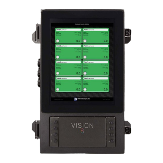
VISION™ 8 Operating Manual 5.1.1 Analysis Mode The ‘Analysis’ screen (see Figure 5.1.1) is entered either automatically during power on or by selecting the ‘Analysis’ option from the Main Menu. General status of all eight points can be viewed here. Figure 5.1.1.a Upon entering Analysis Mode, the VISION™... - Page 26 VISION™ 8 Operating Manual Figure 5.1.1.b The white message box located at the top of the screen provides system status updates as they occur. The logged in username is displayed in the top right corner. The current date & time can be found on the top right, just below the username.
-
Page 27: Setup
VISION™ 8 Operating Manual 5.1.1.a Point Trend Details Touching the any point from the Analysis screen will display point-specific detailed information as shown in Figure 5.1.1.a. The screen details the point #, name, location, range, alarm levels, flow level, current concentration, and a timeline graph of the concentration detected. -
Page 28: Point Configuration
Selecting the History button from the Main Menu will present a screen with tabbed options (Figure 5.1.4) for Events, Concentration, Trend, Video, TWA and Service. These sections provide access to the historical data stored on the VISION 8. Continue to review the following sub sections for additional details on each. IMPORTANT: The VISION 8 stores a limited amount of historical data to an internal hard drive. - Page 29 VISION™ 8 Operating Manual 5.1.4.a History -> Events Selecting the Events option, on the History sub-menu, will pull up a screen in likeness to the one shown in Figure 5.1.4.a. This screen retains a list of the most recent events that occurred. A specifically selected date can be selected using the calendar in the Date field.
- Page 30 VISION™ 8 Operating Manual 5.1.4.b History -> Concentration Touching the Concentration button on the History Menu will bring up the screen similar to Figure 6.1.d.2. This screen displays the concentrations recorded for each point for the data selected on the calendar. Figure 6.1.d.2 DC-ITD-V8MAN01_2023_A DODtec.com...
- Page 31 VISION™ 8 Operating Manual 5.1.4.c History -> Trend Selecting the Trend tab under History will produce a graphical view of either Concentration (‘Conc’ button) or Delta (‘Delta’ button) trends. Trends are display based upon the specific Date and Point selected. Figure 5.1.4.c DC-ITD-V8MAN01_2023_A DODtec.com...
- Page 32 VISION™ 8 Operating Manual 5.1.4.d History -> Video Select the Video tab under History to view live video of a gas stain captured on the ChemLogic cassette. Footage is display based on the specific Date and Point selected. The timeline and other supporting analytical data are displayed below the video capture (Figure 5.1.4.d).
-
Page 33: About
VISION™ 8 Operating Manual Figure 5.1.4.e During analysis the VISION™ 8 stores the TWA information every 8 hours* (referred to as a ‘cycle’) for each installed point. The information is stored on the system’s internal storage device for easy transfer to other systems. -
Page 34: Setup Sub-Menu
There are a total of eight flow adjustment valves (two columns of four, numbered 1 thru 8 – see Figure 5.2.3.a) located on the front panel of the VISION 8. They provide the ability to manually adjust the flow for each Point. - Page 35 VISION™ 8 Operating Manual Figure 5.2.3.a When Flow Adjust is selected under the Setup menu, a screen in likeness to Figure 5.2.3.b appears. Touch the ‘Pumps’ button to turn the pumps on. Press the button again to turn the pumps off. When the button is touched, the flow levels for each installed point are displayed.
-
Page 36: Setup -> History
This information is also accessible via the Main Menu. Additional information can be obtained by referring to Section 5.1.5. 5.2.6 Setup -> Configuration The Configuration section includes multiple tabs (Figure 5.2.6) to customize set up for the VISION 8 system. Figure 5.2.6 5.2.6.a Setup -> Configuration -> Machine The VISION™... - Page 37 VISION™ 8 Operating Manual Figure 5.2.6.a Touching the ‘Gas Family’ button brings up the gas family drop down menu from which you may select the gas family. Touching any of the alarm level numeric displays will bring up the keypad to change the alarm level. The valid alarm levels are listed in Appendix C for each gas.
- Page 38 VISION™ 8 Operating Manual Figure 5.2.6.b Select a desired tab to verify or adjust settings. Once the settings are adjusted, be sure to select the ‘Save Changes’ button. A temporary ‘Point Configuration Changed’ note will appear at the top of the screen to signal the changes were implemented.
- Page 39 VISION™ 8 Operating Manual For each point the Gas type, alarm levels, name, location, description, K Factor, and enabled/disabled may be adjusted. Note that changing the K Factor requires a high level password. The alarm levels will automatically be adjusted to the default levels when the gas time is changed from the drop-down menu.
- Page 40 VISION™ 8 Operating Manual Figure 5.2.6.c.2 IMPORTANT : Default factory passwords from the factory are as follows: Administrator: admin Maintenance: maint 5.2.6.d Setup -> Configuration -> Logging Three components make up the logging configuration of the system: Where to log, What to log, and how often to log.
- Page 41 VISION™ 8 Operating Manual The drop-down list for Concentration Logging Mode gives the operator the three available choices for what None Above LDL concentration data should be logged: = No concentrations; = Those above LDL alarm level; = All concentrations. Only points where gas is detected are logged to the disk. An appropriate event message is always written to the event log when gas exceeds alarm level 1 or 2 on a per point basis.
- Page 42 VISION™ 8 Operating Manual 5.2.6.e Setup -> Configuration -> Network Selecting the ‘Network’ tab will produce a screen in likeness to Figure 5.2.6.e. Ensure the network is configured to the correct address and consult your IT Department for assistance as needed. Select the ‘Edit’ button for a specific adapter to manually update the configuration.
-
Page 43: Setup -> Calibrate Optics
VISION™ 8 Operating Manual IMPORTANT : After configuring, the ”Save Changes” button must be selected in order to update the system. 5.2.6.g Setup -> Configuration -> Custom To establish a custom configuration, select the ‘Custom’ tab from the Configuration screen (Figure 5.2.6.g). Available options include: Restart Analyzer Service •... - Page 44 VISION™ 8 Operating Manual Figure 5.2.7 NOTE: This screen requires the Administrator password for access. DC-ITD-V8MAN01_2023_A DODtec.com REV 5/10/2023 815-788-5200 Page 44 solutions@dodtec.com...
-
Page 45: Chapter 6 - Maintenance And Disposal
VISION™ 8 Operating Manual Chapter 6 – Maintenance and Disposal DANGER : Disconnect power before servicing 6.1 Returning To A Safe State After Service Before returning the VISION™ 8 to service after maintenance or perform verify the following checks: Verify all A/C power connections are secured properly •... -
Page 46: Chemlogic ® Colorimetric Cassette
Each ChemLogic® cassette cartridge for the VISION™ 8 will last up to the specified number of days listed under normal usage (no gas conditions). See Appendix A for ordering information or contact DOD Technologies for assistance. 6.5 ChemLogic Cassette Installation &... - Page 47 9. Promptly dispose of fully used or expired ChemLogic cassettes. The system warranty will be voided if off-brand cassettes or other non-conforming items are inserted into the cassette tray – in lieu of VISION™ 8 ChemLogic® branded cassettes. Contact DOD Technologies for available replacement options.
-
Page 48: End-Of-Line Particular Filters
IMPORTANT : All points require filtration to prevent dust accumulation in tubing and internal damage to the VISION 8. Dust that collects in the tubing or the internal system may cause sample loss and inaccurate gas concentration readings. - Filter For Corrosive Gases - Disposable Filter For –... -
Page 49: Flow Adjustment
VISION™ 8 Operating Manual Description Suggested Replacement DOD Filter Part # AsH3 Arsine 6 Months 780248 B2H6 Diborane 6 Months 780248 GeH4 Germane 6 Months 780248 H2SE Hydrogen Selenide 6 Months 780248 Phosphine 6 Months 780248 SiH4 Silane 6 Months 780248 Tertiary-Butyl-Arsine 6 Months... -
Page 50: Chapter 7 - Service & Support
Cary, IL 60013 E-mail us at: solutions@dodtec.com Visit our website: DODtec.com For permanent discontinuation: Discontinued units may be eligible for recycling. Please contact DOD Technologies for additional information and instructions for arranging safe return of your equipment. DC-ITD-V8MAN01_2023_A DODtec.com REV 5/10/2023 815-788-5200 Page 50 solutions@dodtec.com... -
Page 51: Appendix A - Parts & Accessories
VISION 8 Hydrides 120-Day ChemLogic Cassette 1-300-100 Gas Detected: AsH3, B2H6, GeH4, H2S, H2Se, PH3, SiH4 VISION 8 Mineral Acids SG 120-Day ChemLogic Cassette 1-420-100 Gas Detected: BF3, C4F6, CH2F2, CH3F, HBr, HCl, HF, HNO3, NF3, SF6 VISION 8 Phosgene 120-Day ChemLogic Cassette... -
Page 52: Appendix B - System Specifications
VISION™ 8 Operating Manual Appendix B – System Specifications The VISION™ 8 is designed for safe use under the following conditions: Indoor use only • Altitude up to 2,000 m • Temperature 5ºC - 40 ºC • Maximum relative humidity 80% for temperatures up to 31 ºC decreasing linearly to 50% relative •... -
Page 53: Appendix C - System Event Message
VISION™ 8 Operating Manual Appendix C - System Event Message Color Coding Gas Alarm Fault (Critical) Warning (Non-Critical) Information Message Analysis Status (Good) Event Level Event Code Event Message Corrective Action Alarm 1001 Gas Alarm Level 1 Point # Evacuate point area. Stop release of gas if safe. Alarm 1002 Gas Alarm Level 2 Point #... - Page 54 VISION™ 8 Operating Manual Event Level Event Code Event Message Corrective Action Information 4003 Optics Calibrated Point # Information 4004 Config Changed Point # Information 4005 Machine Config Changed Information 4006 User Logged In Information 4007 User Logged Out Information 4008 User Added Information...
-
Page 55: Appendix D - Gas Specifications
VISION™ 8 Operating Manual Appendix D – Gas Specifications Alarm Alarm ChemLogic Name Gas Family Units Cassette # Default Default 10000 Acetic Acid CH3COOH Acetic Acid 1-700-100 Ammonia Ammonia 1-420-100 Arsenic Pentafluoride^ AsF5 (HF) MA-SG AsHCl3 1-420-100 Arsenic Trichloride^^ (HCl) MA-SG 1-420-100 Arsenic Trifluoride^... - Page 56 Velcorin DMDC Velcorin * Additional ranges may be available and are subject to change. Please review product specifications or contact DOD Technologies. ^ Compounds which hydrolyze to HF ^^ Compounds which hydrolyze to HCl ^^^ Compounds which hydrolyze to HBr DC-ITD-V8MAN01_2023_A DODtec.com...
-
Page 57: Appendix E - Data Communication
Appendix E – Data Communication The VISION™ 8 is capable of supporting Modbus/TCP, Ethernet/IP, ControlNet, Profibus, ProfiNet and OPC communications. For additional information or assistance, please contact DOD Technologies. E.1 – Modbus/TCP DHCP, configurable from the configuration menu. External communications uses topmost Ethernet port. - Page 58 VISION™ 8 Operating Manual Address Type Data Description Notes Words 40165 Float[8] Full Scale Primary Points 1-8 40181 Float[8] Full Scale Secondary 1 Points 1-8 40197 Float[8] Full Scale Secondary 2 Points 1-8 40213 Float[8] Full Scale General Gas Points 1-8 40229 Word[8] Gas ID Primary...
- Page 59 VISION™ 8 Operating Manual Address Type Data Description Format 40019 Bool Tape Advance Fault 40019 Bool All Points Disabled Fault 40019 Bool Optics Fault 40019 Bool Analyzer Communications Fault 40019 Bool Idle Timeout Fault 40019 Bool Gate Open Fault 40019 Bool Analysis Fault 40019...
Need help?
Do you have a question about the VISION 8 and is the answer not in the manual?
Questions and answers