
Related Manuals for Mepu M300k


Summary of Contents for Mepu M300k
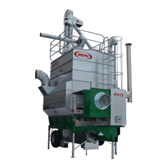
- Page 1 K-SERIES MOBILE DRYER OPERATING MANUAL M180k, M205k, M240k, M275k, M300k, M365k and M420k ID: D00125-2019_EN Rev.A MEPU Oy Mynämäentie 59, 21900 Yläne, Finland p. +358(2) 275 4444, mepu@mepu.com www.mepu.com...
-
Page 2: Table Of Contents
TABLE OF CONTENTS FOREWORD ..........................3 WARRANTY AND WARRANTY TERMS ..............3 Important information for mobile dryer operators ............... 4 Basics of grain drying ........................5 Technical specification of the mobile dryer ................. 6 Hopper and feeding auger conveyor ..................7 Elevator .......................... - Page 3 Concise operating instructions ....................37 In the beginning of the drying season make the following checks ........37 Filling ..........................37 Drying ..........................37 Emptying ..........................38 After the drying season ...................... 38 10 Technical data ..........................39 11 User settings ..........................42 12 Declaration of conformity ......................
-
Page 4: Foreword
The warranty does not cover premature wear or damage of parts resulting from negligent maintenance. Any matters related to warranty and possible expenses have to be pre-agreed with Mepu Oy before performing any repairs. D00125-2019_EN... -
Page 5: Important Information For Mobile Dryer Operators
2 Important information for mobile dryer operators Avoid falling down After having installed the grain silo fasten the ladder and back rails as well as the roof guardrails. Be particularly careful when working on the roof in rain, or if the roof is covered with ice. -
Page 6: Basics Of Grain Drying
3 Basics of grain drying The keeping quality of harvested grain depends on its moisture content and the grain temperature achieved by the method of storage. Under the conditions in Scandinavia and the northern hemisphere, the moisture content of grain after harvesting varies typically between 15–45%, which requires taking measures to improve the keeping quality of grain. -
Page 7: Technical Specification Of The Mobile Dryer
4 Technical specification of the mobile dryer D00125-2019_EN... -
Page 8: Hopper And Feeding Auger Conveyor
4.1 Hopper and feeding auger conveyor Grain is loaded into the filling hopper equipped with a bottom conveyor, which feeds grain to the elevator. In rubber flap elevator models, the feeding auger conveyor features a manual disconnect switch, which allows disconnecting the auger conveyor from the rest of the removal equipment for the time of drying. -
Page 9: Drying Cells
4.5 Drying cells The drying cells have many air ducts. The drying process is uniform, because air is blown into the central channel between the drying cells, from where moist air is discharged through the drying cells towards the sides into the exhaust air cases. In the rear part of the central channel there is a cleaning/ inspection hatch. - Page 10 The feeding apparatus with a cam operated bottom hatch opening mechanism features a separate cam for opening and closing every bottom hatch. In such a feeding apparatus the second and the fifth cam (see Figure) has an intermediate position, which can be used to control the flow of grain into the bottom trough when the hatches are opened with the cam.
-
Page 11: Bottom Trough, And Bottom Aspirator, Sampling Unit
All bottom hatches must be closed during the drying process or filling the dryer! The bottom hatches must not be closed, if there is grain in the bottom trough (risk of damage). The driving engine of the feeding apparatus is an inverter-controlled gear motor, from which the rotating movement is transmitted through the chain drive to the feeding shafts. -
Page 12: Deploying And Positioning Of A Mobile Dryer
5 Deploying and positioning of a mobile dryer. Mobile dryers need not be placed in a building. The design of a mobile dryer permits using it outdoors without any special protective structures. Nevertheless, it is advisable to build a light unheated shelter around the dryer, or an element silo to be used as grain storage, which also gives the structure its walls. -
Page 13: Power Supply
5.2 Power supply The electrical equipment is installed and tested at the factory. The unit is equipped with a 10 m electrical cable with either 32 A or 63 A plugs. If you need more cable, it has to be of the VSEN 5x6 mm type. -
Page 14: Electrical Switchboard
5.3 Electrical switchboard A. Group fuses and earth leakage circuit breaker. The actuators are protected by fuses and an earth leakage circuit breaker. B. Main switch. Under the protective cover. The electrical equipment of the dryer can be disconnected from the power network. The switch must always be turned to OFF position, when any maintenance work is carried out. - Page 15 Overheat Light when overheat limit is reached Engine protection Frequency converter malfunction Channel fans Channel aspirators can be switch off or put on during the drying process. Workpause time relay Activate or deactivate work-pause time relay Feeder speed Adjusts how quickly the grain rotates inside the dryer Channel fans Manual control of the elevator (Operation mode switch 0-position)
- Page 16 Electrical switchboard upper cabinet If the group fuses tend to trip often, contact an electrician to have the unit fixed so that it is safe to use. D00125-2019_EN...
-
Page 17: Oil
5.4 Oil So that the warranty would remain valid for the Oilon oil burner, fixed pipes must be installed to the burner, and the installation work may be carried out only by a company specialised in oil burner installations and approved by Tukes (The Finnish Safety and Chemical Agency). -
Page 18: Dryer Furnace
5.6 Dryer furnace Deployment The furnace installed on the mobile dryer is ready for use, after the on-site electrical and oil circuit connections have been made. Before starting the drying mode, check the following furnace parts: Check that the oil hoses are connected correctly (the arrow on the filter and the pump indicate the suction and return sides). - Page 19 Factory settings Unit Type Factory Action setting Capillary The fan starts when the temperature is Fan thermostat 50 °C exceeded. Always make sure that the dryer power is switched on. Digital Puts the 1 stage flame off at this Burner thermostat 1 stage 90 °C temperature.
-
Page 20: Operating The Dryer
6 Operating the dryer The drying process consists of four different stages. Filling, drying, cooling and emptying. 6.1 Filling the dryer Preparations Before starting the operations determine the suitable trainer dumping height, and remember to set up a block for the trailer, to avoid damaging the hopper. Check the following before dumping: 1. -
Page 21: Drying
6.2 Drying Preparations Check the following before starting the drying process: 1. That the divider is in the drying position. 2. That the conveyor switch on the rear box is in the position 1. See. 3. That the switch cam of the feeding auger is pulled out. 4. -
Page 22: Emptying The Dryer
The feeding apparatus is adjusted to factory settings. This setting should be checked with your own type of grain. If the dryer is used to dry e.g. turnip rape or grain with a higher than normal moisture content, the settings of the feeding apparatus should be modified. Also check the functioning of the pre-cleaner, and change its settings, if appropriate. -
Page 23: Dryer Settings
6.4 Dryer settings 6.4.1 Setting the filling delay The delay time of the level guard can be adjusted on the electrical switchboard. The timer of the level guard is situated in the upper cabinet of the electrical switchboard (10). The filling of the grain bin can be adjusted with the delay of the level guard. -
Page 24: Cooling Timer
6.4.2 Cooling timer The start display of the cooling timer is shown at pos. (A). After the set time has lapsed and the timer has stopped the equipment, the drying process has ended, pos (B). Pos. (C) shows a situation when the Lock (2) key has been pressed, the keys are locked and are released only after the Lock (1) is pressed again. -
Page 25: Work/ Pause Time Relay
6.4.3 Work/ pause time relay The timer is situated on the cover of the electrical switchboard. When starting the drying process note that the burner will ignite after the set pause time. This means that the drying process starts with a pause. In chain elevator machines, factory settings have been set as 60 seconds of operation time for the conveyors, then stopping for 120 seconds to wait for the accumulation of grain on the bottom conveyor. -
Page 26: Setting The Burner Thermostat
6.4.4 Setting the burner thermostat Burner thermostat type: LAE AC1-5TS2RW Function: The thermostat is used to adjust the temperature of the air blown into the dryer. The air temperature is displayed in the thermostat screen during the drying process. Indication: The LED lights located on the right side of the thermostat's numeric display, next to the texts OUT1 and OUT2, show the status of the thermostat keys. -
Page 27: Setting Of The Drying Thermostat
Note that during the drying process the values can vary depending if the outdoor temperature is low. 6.4.5 Setting of the drying thermostat Type of the drying thermostat: LAE LTR-5TSRE Function: The thermostat adjusts the switch-over of the dryer from the drying phase to the cooling phase. -
Page 28: Setting Of The Feeding Apparatus
6.4.6 Setting of the feeding apparatus The feeding amount can be increased or decreased by controlling the frequency converter of the gear motor. If you wish to find out the exact circulation speed, the easiest way to do this is to empty the unit with the feeding apparatus and measuring the time. -
Page 29: Setting The Spreader Disc
When adjusting the levelling plate it should be noted that when the weight is moved towards the shaft, the levelling plate gets lighter, and when it is moved away from the shaft, the levelling plate gets heavier. The appropriate initial setting should be as light as possible, i.e. the position closest to the shaft. -
Page 30: Setting The Air Flow Rate
6.4.9 Setting the air flow rate The air flow can be adjusted with the flap in the suction collar of the furnace fan. The flap is turned towards the closed position, which reduces the air flow. It is not advisable to close the flap completely, unless the batch being dried is particularly small, or if the material is particularly light. -
Page 31: Drying Of Partial Batches
6.4.10 Drying of partial batches If the batch of grain being dried is significantly smaller than the actual capacity of the dryer, there is the risk that as the drying phase progresses and the grain is dried, the top ridges open up into the grain bin. - Page 32 Starting from the M205k model the role of the partial batch shutter is performed by the central shut- off hatch, which cuts off the air flow into the top drying cells or cell parts. In larger models there can be as many as two central shut-off hatches on top of each other. These can be used to divide the dryer volume into three sections.
-
Page 33: Cleaning The Central Channel After Drying A Partial Batch
6.4.11 Cleaning the central channel after drying a partial batch When drying a partial batch, some grain may have ended up on the central hatch. Open the central hatch so that the grain would trickle to the bottom of the central channel. Clean the central channel and the base of the furnace;... -
Page 34: Maintenance
7 Maintenance The dryer's reliability is a crucial factor for ensuring a successful harvest. Possible malfunctions can cause even significant risks. The best way to avoid risks is to ensure that the unit is maintained properly. When cleaning the unit, turn the main switch to OFF. Maintenance and cleaning operations Maintenance and cleaning operations can be divided as follows: 1. - Page 35 Do not overtighten the chain. After tightening the elevator has to rotate rather freely, when you turn the larger pulley by hand. There is a separate maintenance manual for bucket elevators. Furnace Clean and de-soot the dryer furnace immediately after the drying season. The explosion /soot hatch is located on the front wall.
-
Page 36: Malfunctions
8 Malfunctions Below is a short description of some automation and troubleshooting related phenomena. Use the list below to check the object of malfunction and possible actions. If the problem is not cured, please contact the maintenance workshop or the manufacturer. Problem Cause Remedy... - Page 37 The burner has run out of Check oil level The burner does not ignite (when Check the condition of oil hoses the dryer is running). The The fuel filter is clogged Check the hose arrangement burner alarm light is on.
-
Page 38: Concise Operating Instructions
9 Concise operating instructions 9.1 In the beginning of the drying season make the following checks Tightness and condition of the chains and the drive belts The elevator o Check the elevator flaps. Replace, if worn. o Make sure that the elevator and the dryer are aligned. Measure the distance! o Make sure that you have spare belts, flaps and chain links at hand. -
Page 39: Emptying
The burner stops when the exhaust air temperature has risen above the dryer thermostat set value. The burner stops and the cooling phase starts. Check the humidity of the dried grain batch with a special meter and continue the drying phase, if the humidity level is too high. -
Page 40: Technical Data
10 Technical data Chain elevator models Name Type M180k M205k M240k Min. elevator A [m] Height B [m] Air exhaust C [m] Tot. capacity [m3] 16.3 18.4 21.6 Min. drying batch [m3] Dryer machinery [ton] Flow during drying 27.8 Electric power during drying [kW] 13.25 15.25... - Page 41 Bucket elevator models Name Type M180k M205k M205k M240k M275k M300k M365k M420k A [m] 8.25 8.75 8.75 10.5 11.75 13.50 Elevator B [m] Height C [m] Air exhaust [m3] 16.3 18.4 18.4 21.6 25.1 27.2 33.9 39.5 Grain volume Min.
- Page 42 panel storage layers Grain service platform Ladder ø200 Grain 2.0 m circulation pipes Level guard Electrical diagram Installation manual Operating manual Spare parts catalogue D00125-2019_EN...
-
Page 43: User Settings
11 User settings General settings Unit Factory setting User User User settings 1 settings 2 settings 3 Fan thermostat 50 °C °C °C °C Burner thermostat 1 stage 90 °C °C °C °C Burner thermostat 2 stage 80 °C °C °C °C Overheat thermostat... - Page 44 D00125-2019_EN...
-
Page 45: Declaration Of Conformity
12 Declaration of conformity D00125-2019_EN... - Page 46 Mepu Oy:n huoltopalvelu: Puh. (02) 275 4444 / Huolto E-mail: huolto@mepu.com Mepu Oy service: Tel: (02) 275 4444 / Maintenance E-mail: service@mepu.com MEPU Oy Mynämäentie 59, 21900 Yläne, Finland p. +358(2) 275 4444, mepu@mepu.com www.mepu.com D00125-2019_EN...
Need help?
Do you have a question about the M300k and is the answer not in the manual?
Questions and answers