Table of Contents
Advertisement
Advertisement
Table of Contents
Troubleshooting

Related Manuals for Asco 8000 SERIES


Summary of Contents for Asco 8000 SERIES
- Page 1 8000 S Load Banks ERIES User Manual Power Technologies...
- Page 2 © 2000-2018, N J Froment and Co Ltd (‘The Company’). N J Froment and Co Ltd is part of the ASCO Power Technologies business platform. Froment and the Froment logo are trademarks or registered trademarks of N J Froment and Co Ltd . All other names and logos referred to are trade names, trademarks or registered trademarks of their respective owners.
-
Page 3: Table Of Contents
Table of Contents Table of Contents Introduction Transporting Froment 8000 S Load Banks 2 - 4 ERIES • An important note on safety 0 - 2 Lifting by fork lift truck • Lifting by crane or hoist • Transport • Storage Chapter One - Introducing Froment Load Banks •... - Page 4 Operating the Load/Control screen Firmware Updates 4 - 3 Appendicies Connecting the Hand-held to the Load Bank 4 - 3 8300 - Installation Diagrams A - 2 The Hand-held Keypad 4 - 4 8400 - Installation Diagrams A - 5...
-
Page 5: An Important Note On Safety
Chapter One An Important Note on Safety All Froment load banks are designed with safety as a very high priority, but their operation does Introduction present some risks. In common with other test equipment, the safety of all concerned is dependent on the way that the unit is operated. -
Page 6: Chapter One - Introducing Froment Load Banks
Chapter One Introducing Froment Load Banks If you are not familiar with the use of Froment Load Banks then you should start with this chapter. It provides an introduction to the general principles of power supply testing and then it explains how a Froment load bank makes the process easier, safer and more reliable. -
Page 7: Why Is Power Supply Testing Required
Chapter One Introducing Froment Load Banks Why is Power Supply Testing Required? How Do Load Banks Work? There are many different ways of generating electrical power and many reasons why Load banks are complex precision engineered machines, but to explain the general generating equipment may be required. -
Page 8: Introducing Froment Load Banks
Chapter One Introducing Froment Load Banks Introducing Froment Load Banks Froment Load Bank Control Options Froment load banks are purpose designed to provide all of the facilities needed to quickly, Reliable testing requires precise control of the load applied to the generator and accurate safely and reliably test generating equipment with outputs up to several megawatts. - Page 9 Chapter One Introducing Froment Load Banks Decade switch local control panel. The simplest form of control is via a series of decade switches mounted on the unit’s switchplate or on a remote control panel. These provide basic manual control and are only available on units fitted with purely resistive load elements.
-
Page 10: Non-Unity Power Factor Testing
Chapter One Introducing Froment Load Banks Non-unity Power Factor Testing When is non unity power factor testing required? It is unusual for a generator to be presented with a purely resistive load. In real-world This depends on the type of test that is required. applications it is much more likely that the load is made up of a combination of resistive, inductive and capacitive elements (electric motors, lamp ballasts, etc.) which may be Sometimes, for smaller generators where a standardised alternator design is in use, the... -
Page 11: Movable Load Banks
Chapter One Introducing Froment Load Banks Movable Load Banks Power supply selector switch. The load bank switch panel is fitted with a selector switch, allowing easy selection between Off, Internal supply (generator under test) or external (Auxiliary) supply. The switch is not fitted where the load system is designed for a supply Many Froment load banks are supplied for applications where they will be permanently that is incompatible with the fan supply, for example, on low voltage AC, DC, or 400Hz load installed at a particular site location. -
Page 12: Load Bank Applications
Chapter One Introducing Froment Load Banks Load Bank Applications Testing UPS systems and batteries The main application for a load bank is for use during generator testing. However, load Uninterruptable power supply systems consisting of a generating set combined with a set banks are versatile devices and they have a number of useful applications that can be of batteries are a common feature of data centres and other installations where maintaining applicable during the installation, commissioning and ongoing operation of a generator. -
Page 13: Using Multiple Load Banks
Chapter One Introducing Froment Load Banks Using Multiple Load Banks Control Signal Froment’s Sigma control system allows up to fourteen load banks to be interconnected and controlled from a single terminal as if they were a single unit. This means that multiple load banks can be combined to match particularly large generating sets, or that a combination Load Bank of resistive, capacitive or inductive loads can be mixed for special purpose or one-off tests. -
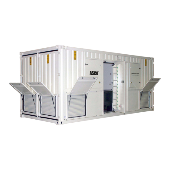
Page 14: Introducing Froment 8000 Series Load Banks
Froment. In standard form they are Sigma controlled, combined (resistive/ table describes standard equipment for the 8300 and 8400, but there are many custom options and configurations reactive) load banks with capacity ranging from 3300 kVA (8300) to a maximum of around available. -
Page 15: Chapter Two - Load Bank Installation And Setup
Chapter One Hot air exhaust Resistive load elements Switchgear cabinet Chapter Two Load Bank Installation and Setup This chapter covers all of the procedures that need to be carried out before a Froment load bank can be put into operation. It explains how to install the unit safely and how to commission it to check that it will operate correctly. -
Page 16: Using A Froment Load Bank Safely
Chapter Two Load Bank Installation and Setup Using a Froment Load Bank Safely • Lay the cables to minimise the risk of personnel tripping or accidentally tugging on the cables. Your safety, and the safety of those around you, is dependent on your knowledge of this •... -
Page 17: Transporting Froment 8000 Series Load Banks
• If the 8300 is to be shipped by sea it will require a 20ft cradle to allow it to be handled by dockside cranes at the shipping port. •... -
Page 18: Installing Froment Load Banks
Chapter Two Load Bank Installation and Setup Installing Froment Load Banks Sound attenuators There are a number of factors that need to be considered before you select a load bank Please contact our sales department for advice if you intend to fit a sound attenuator to for a particular installation. -
Page 19: Electrical Installation
Short • Circuit Protective The work must be carried out by a person with the appropriate training, qualifications The external supply socket for the 8300 is mounted externally (see appendix drawings for Device (SCPD), which and experience. the exact location). -
Page 20: Anti-Condensation Heaters And Lighting Supply
Chapter Two Load Bank Installation and Setup Connecting the Supply-on-Test If you are making use of this external supply socket, switch the 3-position supply selection switch to the “External” position. The cables for the Supply-on-Test can be fed into the load bank through cable sock Note: The terminal bars openings in front of the power terminal compartment, or through the bottom of the can accept both copper... -
Page 21: Making Connections For Single-Phase Operation
Chapter Two Load Bank Installation and Setup Supply-on-test wiring - general points External voltage metering source. This input connector is used to connect the load bank’s instrumentation directly to the Supply-on-Test. This provides more accurate instrumentation, avoiding problems of voltage drop when long supply cables are used. •... -
Page 22: Control System Connections
Chapter Two Load Bank Installation and Setup Basic Connection In this case the connection will provide approximately 67% loading capacity when a 400V single-phase supply is connected or 22% loading capacity when a 230V single-phase supply is used. The basic connection shown in Figure 2-6 will give approximately 50% loading capacity when the nominal load bank supply voltage is connected or 17% loading capacity when a Control System Connections 230V single-phase supply is used. -
Page 23: Commissioning
Chapter Two Commissioning Before operating the load bank carry out the following three-stage commissioning procedure. Chapter Three Visual inspection and safety check. Inspect the load bank and ensure that: Load Bank Operation • All terminations are secure and correctly wired. This chapter explains how to operate the load bank’s local control panel. -
Page 24: Before Operating The Load Bank
Chapter Three Load Bank Operation Before Operating the Load Bank Controlling the load bank Ensure that: The control room switches allow the load bank’s power source to be selected, and provide local on/off control and manual emergency shutdown. However, during load testing the load bank is controlled using the Sigma 2 load control system. -
Page 25: The Control Room
ERIES optional spring motor powered air circuit breakers for the Supply-on-Test connections. The 8300 has a single circuit breaker and the 8400 has two. Refer to the documentation provided with the circuit breakers for further information. Fan and controls supply isolator. -
Page 26: Main Control Panel
Chapter Three Load Bank Operation Main control panel The main control panel for the load bank is located on the left at the back of the control ∑ Sigma 2 room. The specific controls provided can vary from model to model — the arrangement Control shown in Figure 3-2 shows a typical configuration for the left hand side of the panel and Figure 3-3 shows a typical arrangement for the right hand side. -
Page 27: Operating The Optional Air Circuit Breakers (Acbs)
Chapter Three Load Bank Operation Operating the optional air circuit breakers (ACBs) Status indicator lamp operation The circuit breaker spring motor must be fully charged before its contacts can be closed: The control panel contains a number of status indicator lamps. These include a lamp (two Note: When the ter- lamps in the case of the 8400) which indicates the status of the Air Circuit Breakers (ACBs). -
Page 28: Emergency Shutdown Procedures
Chapter Three Load Bank Operation Emergency Shutdown Procedures Warnings. A warning will alert you to an abnormal condition such as high temperature, but will allow the unit to continue to run if required. The load bank provides two methods of quickly shutting down the load bank in an General load bank warnings are indicated by the Stop indicator lamp flashing continuously. -
Page 29: Load Function Test
Chapter Three Load Bank Operation Load Function Test Note: The Start lamp 8. Check the rotation direction of the fan. Movable load banks are fitted with automatic will blink if you are phase rotation sensors and will adjust the direction of rotation accordingly. On static using the load bank units the fan may run in the reverse direction if the phases are wired in the wrong Immediately after the installation has been completed run a brief load function test to... -
Page 30: Load Bank Emergency Operation
Load Bank Operation Chapter Three Load Bank Emergency Operation Load Bank Operation Using a Remote Station If a Sigma 2 controller is unavailable it is possible to use the load bank ID rotary switch to The remote control station duplicates some of the controls on the main control panel and control the load bank. - Page 31 Chapter Four SIGMA Hand-held Reference Guide The SIGMA Hand-held provides a very simple to use, direct means of controlling the operation of Sigma controlled load banks whilst simultaneously monitoring the performance of the generator under test. This chapter provides an in-depth look at the hand-held control system with an overview of its more advanced features.
-
Page 32: The Sigma Hand-Held
Making sure the firmware is up to date on the Sigma Hand-held is important to maximise ASCO Froment load banks. It is a hand-held unit containing a purpose designed load testing capabilities and ensure correct operation. The Sigma Hand-held has a micro microprocessor-based control system for Sigma-equipped load banks. -
Page 33: Connecting The Hand-Held To The Load Bank
Chapter Four Chapter Four Connecting the Hand-held to the Load Bank The Hand-held Keypad The Hand-held connects directly to the load bank’s Sigma control “in” socket using a The keypad contains eight membrane switches and a single LED indicator. The switches Sigma control cable which can be up to a kilometre in length. -
Page 34: The Hand-Held Menu Display System
Hand-held Reference Guide Chapter Four The Hand-held Menu Display System The following table lists the messages that may appear: The Hand-held uses a menu display system for initial settings and also during the testing Error Message Description Possible Causes • process. -
Page 35: Using The Sigma Hand-Held
Hand-held Reference Guide Chapter Four Using the Sigma Hand-held Hand-held Quick Start The Hand-held’s on screen menu system is designed to be simple and intuitive, and the best way to learn it is to use it. The quick-start demonstration on the following page shows Press the start button on the how you can carry out a full manual generator test with only a few key presses. -
Page 36: Using The Settings Pages
Hand-held Reference Guide Chapter Four Using the Settings Pages Settings 1 - Supply-on-test Before testing begins it is important to set up the Hand-held so that it is able to control The Settings 1 page is used to set up the details of the Supply-on-Test and it is important the load bank correctly. - Page 37 Hand-held Reference Guide Chapter Four Checking the rating values To edit the supply rating values: 1. On entering the Supply-on-test Edit page the kVA value will be highlighted, ready for The voltage, frequency and number of phases set are the Sigma Hand-held’s best estimate editing.
-
Page 38: The Options Page
Hand-held Reference Guide Chapter Four Settings 2 - Load bank The Options Pages The load bank settings page shows the number and total maximum capacity of all the load There are three options pages which will allow you to adjust various aspects of the load banks under control of the Hand-held. -
Page 39: The Test Pages
Hand-held Reference Guide Chapter Four Options 1 - Control: Instrumentation. Lets you override the default resolution for current and power instrumentation. The default resolution for instrumentation is determined by the load bank size and minimum load step. For example it could be in tenths of kW or whole kW or tens of kW. -
Page 40: The Test Pages
Hand-held Reference Guide Chapter Four The Test Pages Test 1 - AVR and governor adjustment setup There are three Test pages which allow you to select and accept load, and to monitor the Apparent Power Real-time voltage and test as it proceeds. To reach the first of them, press F4 (TEST) from either of the Settings frequency display Pages. - Page 41 Hand-held Reference Guide Chapter Four Test 3 - Full load testing (phase to neutral) Assessing supply performance RMS Current The voltage and frequency maximum and minimums and transient response graphs can Real-time voltage and RMS line to line voltage be used to assess the performance of the Supply-on-Test. frequency display Apparent Power ISO8528 defines three classes of generator performance (G1, G2 and G3) and specifies...
-
Page 42: Manual Test Mode
Hand-held Reference Guide Chapter Four The test screen status bar Manual Test Mode The status bar provides important information during testing. The information shown The Hand-held’s manual test mode provides direct, real time control over the load bank’s varies depending on the test mode (manual or automatic) as shown in Figure 4-20. operation. - Page 43 Hand-held Reference Guide Chapter Four Setting the load values To set the load: Begin by setting the value of the load that is to be applied by using the Hand-held’s + and - By default, the Hand-held allows you to set the load as a percentage of the Supply-on-Test keys.
- Page 44 Hand-held Reference Guide Chapter Four Applying the load Automatic Test Mode 1. Press I to apply the load selected. The Hand-held will calculate the correct load to The Hand-held’s automatic load control function will allow you to set up a pre-programmed Note: If load correction is turned on, then the apply and distribute this between all the connected load banks.
- Page 45 Hand-held Reference Guide Chapter Four Editing the automatic test sequence To edit the test sequence: 1. Press F1 (NEXT) to choose the sequence stage to be programmed. Press F2 (AUTO) from any of the Manual test pages to switch to automatic test mode. Then press F3 (EDIT TEST) to set up the test sequence stages.
-
Page 46: Chapter Five Maintenance & Troubleshooting
Hand-held Reference Guide Running the automatic sequence To run the test sequence press the I key. The green LED on the Hand-held will begin to Chapter Five flash to indicate that the test sequence is running and the status bar will indicate the current stage of the test. -
Page 47: Safety Warning
Chapter Five Maintenance & Troubleshooting Safety Warning Routine Maintenance Procedures Maintenance work should be undertaken only by qualified personnel who are fully aware To keep the load bank in good working order, carry out the following maintenance tasks at of the danger involved and who have taken adequate safety precautions. the specified intervals: Always isolate all the supplies to the equipment before inspecting, moving equipment, Daily (after transportation or before each use of the load bank):... -
Page 48: Air Circuit Breaker (Option) Maintenance
Chapter Five Maintenance & Troubleshooting Fault Finding In addition, carry out a load check to ensure that load contactors and elements are Note: The recom- operating correctly: mended interval for a The following chart covers some of the typical faults you might encounter and some calibration check is one 1. -
Page 49: Sigma 2 Load Bank Status Display
Chapter Five Maintenance & Troubleshooting Sigma 2 Load Bank Status Display Warnings The load bank status is displayed on the seven segment LED located on the Sigma 2 load If an event occurs that generates a warning the load bank Stop button lamp will begin to bank module. - Page 50 Chapter Five Maintenance & Troubleshooting Errors Code Description Possible causes / actions Fan supply voltage and/or frequency limits exceeded Fan supply voltage or frequency is out of limits. If an error occurs the load bank Stop button lamp will begin to flash and a three step on pressing the load bank start button.
-
Page 51: Froment Load Bank System Monitor
Chapter Five Maintenance & Troubleshooting Froment Load Bank System Monitor Code Description Possible causes / actions Supply-on-test over voltage. The Supply-on-Test voltage has exceed the load bank limits. The optional System Monitor is a touchscreen based operator interface panel for 8000 •... -
Page 52: The Meters Screen
Chapter Five Maintenance & Troubleshooting The Meters Screens The System Monitor’s Meter Screen has three tabs (Overview, Supply and Control). Meters/ Overview is displayed by default. Figure 5-4 The Meters/Control screen shows details of the Fan and Controls Supply and the Load Control status. -
Page 53: Status Screen
Chapter Five Maintenance & Troubleshooting Status Screen Tapping the Status key opens the Status screen, which normally has two tabs, Overview and History. Figure 5-6 Tapping an input or output key opens a pop-up window with more detailed information. The I/O screens show the state of each input or output. These are shown green when they are active. -
Page 54: Load Screen
Chapter Five Maintenance & Troubleshooting Load Screen If an error or warning occurs an additional tab will appear and the display will jump to that screen. Tapping the Load key will bring up a screen with two tabs that can be used to operate the Note: It is important load bank during maintenance procedures. -
Page 55: Operating The Load/Control Screen
Chapter Five Operating the load/control screen • Use the Load Control source selector (on the Load/Supply screen) to select “LOCAL” Appendices Note: The System control. Monitor’s load control • will not work if the load Use the + and — keys to adjust the values for kVA, KW, and power factor. bank communications •... -
Page 56: 8300 - Installation Diagrams
(5000) Fork lift pocket centres (1000) Figure A-3 8300 - Plan view showing access clearance requirements Figure A-1 8300 - Side view showing maintenance access and the fork lift pocket locations. Maintenance access door 2591 Cable termination access Cable entry... -
Page 57: 8400 - Installation Diagrams
Appendices 8400 - Installation Diagrams Maintenance access doors Figure A-5 8300 - End view showing air intake louvres and maintenance access doors. Figure A-6 8400 - Front View showing control room access and external supply inlet. Hot air exhaust Hot air exhaust... -
Page 58: Certificate Of Conformity
Appendices Appendices EU Declaration of Conformity Certificate of Conformity Alternative bottom cable entry gland plate Product: Load Bank Name of Manufacturer: N J Froment & Company Limited, Easton-on-the-Hill, STAMFORD, PE9 3NP, United Kingdom Telephone +44 (0)1780 480033 e-mail admin@froment.co.uk Website www.froment.co.uk Country of Origin United Kingdom... -
Page 59: Electromagnetic Compatibility
Appendices Appendices Electromagnetic Compatibility Useful Equations This equipment has been designed and constructed to comply with the European Community Directive 89/336/EEC. To ensure that the requirements of the Directive and Apparent Power (kVA) related standards are satisfied it is essential that the equipment is used as intended and in kVAr full accordance with the operating instructions. - Page 60 ASCO Power Technologies - Froment Load Banks Cliffe Road Easton-on-the-Hill Stamford United Kingdom Tel: +44 (0) 1780 480033 froment.sales@ascopower.com www.ascopower.com loadbanks.ascopower.com ©2018 ASCO Power Technologies. All Rights Reserved. Publication No. 5038 v1.3 ASCO. Innovative Solutions.
Need help?
Do you have a question about the 8000 SERIES and is the answer not in the manual?
Questions and answers