Table of Contents
Advertisement
Quick Links
Advertisement
Table of Contents

Related Manuals for Asco Froment 8800 Series

Summary of Contents for Asco Froment 8800 Series
- Page 1 8800 S High Voltage Load Banks ERIES User Manual Power Technologies...
- Page 3 Froment and the Froment logo are trademarks or registered trademarks of N J Froment and Co Ltd . All other names and logos referred to are trade names, trademarks or registered trademarks of their respective owners. The ASCO and ASCO Power Technologies marks are owned by Emerson Electric Co. or its affiliates and utilized herein under license. ©2017 ASCO Power Technologies.
-
Page 4: Table Of Contents
Table of Contents Introduction An important note on safety 0 - 2 Chapter One - Introducing Froment Load Banks Why is Power Supply Testing Required? 1 - 2 • How can a generator be tested effectively? • The load bank How do load banks work? 1 - 3 Introducing Froment Load Banks... - Page 5 Table of Contents Transporting Froment 8800 S Load Banks 2 - 4 ERIES • Lifting by crane or hoist • Transport • Storage • Packaging Installing Froment Load Banks 2 - 5 • Location • Sound attenuators • Avoiding hot air re-circulation Electrical Installation 2 - 8 •...
- Page 6 Table of Contents Chapter Four - Hand-held Reference Guide The Sigma Hand-held 4 - 2 Firmware Updates 4 - 3 Connecting the Hand-held to the Load Bank 4 - 3 The Hand-held Keypad 4 - 4 The Hand-held Menu Display System 4 - 5 Using the Sigma Hand-held 4 - 8...
- Page 7 Table of Contents Sigma 2 Load Bank Status Display 5 - 6 • Sigma 2 normal operation • Warnings • Errors Froment Load Bank System Monitor 5 - 11 • Startup Screen • Navigation • The Meters Screen • I/O Screen •...
-
Page 8: Introduction
Introduction This manual provides you with all the information that you need to safely install and operate Froment 8800 S load banks. High voltage equipment can be dangerous, please ensure you have followed ERIES all local rules and regulations regarding working with high voltage. The manual is divided into five chapters: Chapter One provides an introduction to the general principles of power supply testing... -
Page 9: An Important Note On Safety
Chapter One An Important Note on Safety All Froment load banks are designed with safety as a very high priority, but their operation does present some risks. In common with other test equipment, the safety of all concerned is dependent on the way that the unit is operated. -
Page 11: Chapter One - Introducing Froment Load Banks
Chapter One Introducing Froment Load Banks If you are not familiar with the use of Froment Load Banks then you should start with this chapter. It provides an introduction to the general principles of power supply testing and then it explains how a Froment load bank makes the process easier, safer and more reliable. -
Page 12: Why Is Power Supply Testing Required
Chapter One Why is Power Supply Testing Required? There are many different ways of generating electrical power and many reasons why generating equipment may be required. All of them have at least one thing in common: it is essential that the generator be capable of operating effectively at its maximum rated output when it is required. -
Page 13: How Do Load Banks Work
Introducing Froment Load Banks How Do Load Banks Work? Load banks are complex precision engineered machines, but to explain the general principal we can provide a very simple model of how they work: Figure 1-1 Basic DIY generator output test system. Figure 1-1 shows the general arrangement of a very basic DIY generator testing system. - Page 14 Chapter One Introducing Froment Load Banks Froment load banks are purpose designed to provide all of the facilities needed to quickly, safely and reliably test generating equipment with outputs up to several megawatts. Load Elements Step 1 Step 1 Step n Cold air Hot air inlet...
-
Page 15: Froment Load Bank Control Options
Introducing Froment Load Banks Froment Load Bank Control Options Reliable testing requires precise control of the load applied to the generator and accurate real-time measurement of the generator’s output. To achieve this, most Froment load banks are fitted with a Sigma 2 load control system. Sigma 2 is a microprocessor-based control and instrumentation system specifically developed for load bank applications. - Page 16 Chapter One Sigma Hand-held. The Hand-held provides load control and instrumentation on Sigma controlled load banks. Figure 1-5 Sigma Hand-held The Hand-held contains a membrane keyboard and built in display unit and is connected to the load bank by a control cable.
- Page 17 Introducing Froment Load Banks Figure 1-6 Sigma PC Load Control Software Sigma Modbus Interface. Every Sigma controlled load bank has the capability to be Note: Both the Hand- held and the PC soft- remotely controlled using the industry standard Modbus serial communications protocol. ware can control up to This will allow the load bank to be integrated with a wide range of test, automation, 14 Sigma controlled load...
-
Page 18: Non-Unity Power Factor Testing
Chapter One Non-unity Power Factor Testing It is unusual for a generator to be presented with a purely resistive load. In real-world applications it is much more likely that the load is made up of a combination of resistive, inductive and capacitive elements (electric motors, lamp ballasts, etc.) which may be continuously changing as various items of equipment are switched on and off. -
Page 19: When Is Non Unity Power Factor Testing Required
Introducing Froment Load Banks When is non unity power factor testing required? This depends on the type of test that is required. Sometimes, for smaller generators where a standardised alternator design is in use, the electrical performance of the alternator and control gear can be assumed to be adequate. In this case the only requirement during testing is to prove that the motive source of the generating set is capable of operating at full power without overheating and a purely resistive load is all that is required. -
Page 20: Movable Load Banks
Chapter One Movable Load Banks Many Froment load banks are supplied for applications where they will be permanently installed at a particular site location. However, in some applications the load bank is as a temporary measure that is only required whilst generator tests are carried out. This is quite common, for instance, with a new generator installation where the load bank is used during commissioning and acceptance testing. - Page 21 Introducing Froment Load Banks Power supply selector switch. The load bank switch panel is fitted with a selector switch, allowing easy selection between Off, Internal supply (generator under test) or external (Auxiliary) supply. The switch is not fitted where the load system is designed for a supply that is incompatible with the fan supply, for example, on low voltage AC, DC, or 400Hz load banks.
-
Page 22: Load Bank Applications
Chapter One Load Bank Applications The main application for a load bank is for use during generator testing. However, load banks are versatile devices and they have a number of useful applications that can be applicable during the installation, commissioning and ongoing operation of a generator. Generating set testing The specific tests that need to be carried out for a particular installation depend on local regulations, the application, the type of equipment involved and the requirements of... -
Page 23: Testing Ups Systems And Batteries
Introducing Froment Load Banks Testing UPS systems and batteries Uninterruptable power supply systems consisting of a generating set combined with a set of batteries are a common feature of data centres and other installations where maintaining a constant power supply is critical. In the event of a power failure the batteries provide an immediate source of power whilst the generator is automatically started, synchronised to the correct frequency and put online. - Page 24 Chapter One Control Signal Load Bank Current Transformer Site Load Generator Utility Supply Figure 1-10 Example layout for a typical Site Load Correction system. The load bank starts up when the generator begins to operate and its control circuits begin to monitor the output current. If this is below a certain set point then the load bank will slowly apply additional load to bring the generator within the optimum range.
-
Page 25: Using Multiple Load Banks
Introducing Froment Load Banks Using Multiple Load Banks Froment’s Sigma control system allows up to fourteen load banks to be interconnected and controlled from a single terminal as if they were a single unit. This means that multiple load banks can be combined to match particularly large generating sets, or that a combination of resistive, capacitive or inductive loads can be mixed for special purpose or one-off tests. -
Page 26: Introducing Froment 8800 Series Load Banks
Chapter One Introducing Froment 8000 S Load Banks ERIES The 8000 S load banks are currently the largest capacity self-contained load banks ERIES supplied by Froment. In standard form they are Sigma controlled, combined (resistive/ reactive) load banks with capacity ranging from 3300 kVA (8300) to a maximum of around 6000 kVA (8400). -
Page 27: 8800 Series
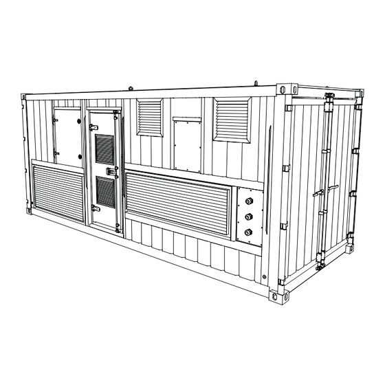
Introducing Froment Load Banks 8800 S Load Bank Specifications ERIES Froment load banks are constructed to suit customers specifications for a particular application. The following table describes standard equipment for the 8800, but there are many custom options and configurations available. Please contact Froment sales office for more details. - Page 28 Chapter One Resistive load Hot air exhaust Switchgear cabinet elements Reactive load elements Control room access door Ring Main Unit Transformer Transformer air exhaust CT’s Figure 1-12 Froment 8800 load bank - cutaway view showing major components 1 - 18...
-
Page 29: Chapter Two - Load Bank Installation And Setup
Chapter Two Load Bank Installation and Setup This chapter covers all of the procedures that need to be carried out before a Froment load bank can be put into operation. It explains how to install the unit safely and how to commission it to check that it will operate correctly. -
Page 30: Using A Froment Load Bank Safely
Chapter Two Using a Froment Load Bank Safely Your safety, and the safety of those around you, is dependent on your knowledge of this equipment’s safe operating procedures. Load banks can be dangerous and must not be used by unskilled personnel, or by those who have not familiarised themselves with these instructions. - Page 31 Load Bank Installation and Setup • Lay the cables to minimise the risk of personnel tripping or accidentally tugging on the cables. • Keep all personnel who are not directly involved with tests well away from the load bank and the equipment under test. •...
-
Page 32: Transporting Froment 8800 Series Load Banks
Chapter Two Transporting Froment 8800 S Load Banks ERIES The 8800 load bank weighs approximately 20000kg (see the rating plate for the exact weight). They require a hoist, forklift or other lifting equipment to move them. Both sizes are fitted with standard ISO twistlock lifting points and are supplied with optional CSC certification for top-loading shipping. -
Page 33: Installing Froment Load Banks
Chapter Two Installing Froment Load Banks There are a number of factors that need to be considered before you select a load bank for a particular installation. Obviously it is important to ensure that the load bank has sufficient electrical capacity to test the supply, but you also need to ensure that it can operate correctly and safely in the position you have chosen. -
Page 34: Avoiding Hot Air Re-Circulation
Load Bank Installation and Setup Avoiding hot air re-circulation Careful consideration should be given to the likely effect of nearby buildings, walls or even parked vehicles, which could seriously disrupt the free escape of hot air, and result in hot air re-circulation. -
Page 35: Electrical Installation
Chapter Two Electrical Installation The electrical installation for a 8800 S load bank consists of making connections for ERIES the Supply-on-Test, an external supply used to power the load bank’s fans and control system and, finally, a single phase supply that provides power for the control room lights and cabinet heaters. -
Page 36: Voltage And Frequency Ratings
Load Bank Installation and Setup Voltage and frequency ratings It is important to realise that the external supply required for the fans and controls may be of a different voltage or frequency from the Supply-on-Test. The voltage and frequency ratings are specific to the equipment supplied and are shown on the rating plate. Exceeding the voltage ratings or supplying the wrong frequency can cause damage to the load bank so please check the plate carefully before starting the installation. -
Page 37: Connecting The Supply-On-Test
Load Bank Installation and Setup Connecting the Supply-on-Test The load bank is fitted with a blank aluminium gland plate which allows access to the HV compartment. Located directly behind the gland plater are the HV CTs, cables should be fed into the load bank through the CT’s and securely fastened to the cable support rails. The cables should be routed under the RMU to the cable connection points shown below. -
Page 38: Supply-On-Test General Points
Chapter Two Supply-on-test wiring - general points • The cable lugs should be clamped directly to the RMU connection points ensuring all securing nuts are tight. Lug connections should be torqued to 54 Nm. • It is good practice to route the three phase conductors in a close trefoil layout, held together with correctly rated cable cleats. -
Page 39: Control System Connections
Froment Chapter Two Load Bank Control System Connections The 8800 Load bank can be operated in multiple ways. High Voltage (HV) Instrumentation mode EMERGENCY STOP In HV instrumentation mode the load bank is operated using the Sigma PC system connected to the Sigma cable socket, located in the external power inlet compartment. START RESET The instrumentation selection switch located on the internal control cabinet door will need... -
Page 40: System Monitor Control
Load Bank Installation and Setup System Monitor Control (HMI) Alternately the load bank can be controlled using the load bank system monitor, this is a touch screen HMI interface panel located on the internal control cabinet door. This can also be used remotely by connecting into the RJ45 Ethernet connector located on the external power inlet compartment. -
Page 41: Commissioning
Chapter Two Commissioning Before operating the load bank carry out the following three-stage commissioning procedure. Visual inspection and safety check. Inspect the load bank and ensure that: • All terminations are secure and correctly wired. • All cables are positioned and safely secured. •... - Page 42 Load Bank Installation and Setup 2 - 14...
-
Page 43: Chapter Three Load Bank Operation
Chapter Three Load Bank Operation This chapter explains how to operate the load bank’s local control panel. It describes the function of each control and explains the operation of the status indicator lamps. It then provides specific examples of how the control panel is used to carry out a load function test and how it can be used to operate the load bank when an external control system (such as the Hand-held) is not available. -
Page 44: Before Operating The Load Bank
Chapter Three Before Operating the Load Bank Ensure that: • The load bank has been installed according to the instructions and safety warnings in Chapter Two. • The external supply (for fans and controls) is connected according to the instructions in Chapter Two. -
Page 45: Controlling The Load Bank
Load Bank Operation Controlling the load bank The control room switches allow the load bank’s instrumentation (see figure 3-1 point 10) to be selected, and provide local on/off control and manual emergency shutdown. However, during load testing the load bank is controlled using the Sigma 2 load control system. Alternatively, the load bank may be controlled with third party software using the HMI ethernet output. -
Page 46: The Control Room
Chapter Three The Control Room The control room houses the cabinets containing the load bank switchgear, the external power supply sockets, a number of local controls and connectors for external equipment. At the rear of the control room is a console, which provides a desktop surface for laptop computers, monitoring equipment, etc. -
Page 47: The External Power Inlet Compartment
Load Bank Operation The lower front surface of the console contains the following: Fan and controls supply isolator. This performs a similar function to the emergency stop button located by the control room door. It is the “on” switch for the load bank control system but can also be used to interrupt testing in the event of an emergency. -
Page 48: Main Control Panel
Chapter Three Remote connection point. This provides the user with options to start, stop and reset faults for the load bank from a remote location. Also included is a remote trip for the ring main unit and a signal to indicate if the load bank is running. RJ45 Ethernet port. - Page 49 Load Bank Operation Start & Reset buttons. The Start and Reset push buttons are used to enable and disable the load bank’s control system. They are also used to reset any error conditions (such as over-voltage or over-temperature) that may have caused an automatic shutdown. Both buttons contain indicator lamps that show the load bank’s status.
-
Page 50: System Monitor
Chapter Three Power outlet sockets and RCD. The panel contains two socket outlets that can be used to power personal computers or test gear (maximum 2 amps). Lighting supply on/off switch. This selects whether the light switch is on or off. System monitor The optional System Monitor is a touchscreen based operator interface panel that provides a number of important system maintenance functions for the load bank. -
Page 51: Status Indicator Lamp Operation
Froment Load Bank Load Bank Operation Status indicator lamp operation The control panel contains a number of status indicator lamps. These include a lamp which indicates the status of the ring main unit (RMU). EMERGENCY STOP START RESET Remove load and allow elements to cool before stopping the fan. - Page 52 Chapter Three To reset the error condition. Stop the load bank and clear the cause of the fault. Press the Reset button followed by the Start button. The load bank will resume operation if the fault has been cleared correctly. The following table summarises the indicator lamp operation: Start Reset...
-
Page 53: Emergency Shutdown Procedures
Load Bank Operation Emergency Shutdown Procedures The load bank provides two methods of quickly shutting down the load bank in an emergency: Emergency stop button. The emergency stop button, located in the control room, is a latching mushroom type push button. The load is removed and the fan will stop running, but the control system remains powered. -
Page 54: Load Function Test
Chapter Three Load Function Test Immediately after the installation has been completed run a brief load function test to confirm that the load bank has been installed correctly and that it is fully operational. This involves running the load bank for a few minutes with a load applied. If the load bank operates normally without any errors and the fan rotates in the correct direction then you are ready to proceed with your testing program. - Page 55 Chapter Four SIGMA Hand-held Reference Guide (For LV use) The SIGMA Hand-held provides a very simple to use, direct means of controlling the operation of Sigma controlled load banks whilst simultaneously monitoring the performance of the generator under test. This chapter provides an in-depth look at the hand-held control system with an overview of its more advanced features.
-
Page 56: The Sigma Hand-Held
The Sigma Hand-held The hand-held is one of a number of available user interface options for Sigma controlled ASCO Froment load banks. It is a hand-held unit containing a purpose designed microprocessor-based control system for Sigma-equipped load banks. The hand-held has a IP65 rated enclosure with a custom-designed membrane keyboard and 4.3”... -
Page 57: Firmware Updates
Hand-held Reference Guide Firmware Updates Making sure the firmware is up to date on the Sigma Hand-held is important to maximise load testing capabilities and ensure correct operation. The Sigma Hand-held has a micro USB port to enable firmware to be updated from a USB flashdrive. The current version of the firmware is displayed on start up in the bottom right corner of the screen. -
Page 58: Connecting The Hand-Held To The Load Bank
Chapter Four Connecting the Hand-held to the Load Bank The Hand-held connects directly to the load bank’s Sigma control “in” socket using a Sigma control cable which can be up to a kilometre in length. The Hand-held can connect to and control up to 14 load banks at the same time. -
Page 59: The Hand-Held Keypad
Chapter Four The Hand-held Keypad The keypad contains eight membrane switches and a single LED indicator. The switches provide four function keys (marked F1 to F4) arranged below the screen and a quadrant of four control keys arranged around the LED. The function keys The operation of the function keys is context dependant. -
Page 60: The Hand-Held Menu Display System
Hand-held Reference Guide The Hand-held Menu Display System The Hand-held uses a menu display system for initial settings and also during the testing process. The screen provides real-time instrumentation readings, status information and labels for the four function keys (F1 to F4). The screen shows details of the supply settings, built-in help and also provides access to instrumentation to allow monitoring during testing. - Page 61 Chapter Four The following table lists the messages that may appear: Description Possible Causes Error Message • Stop Pressed on Load Bank nn Load bank emergency stop signal is Start button has not been pressed or was pressed before the load bank had performed present.
-
Page 62: Using The Sigma Hand-Held
Hand-held Reference Guide Using the Sigma Hand-held The Hand-held’s on screen menu system is designed to be simple and intuitive, and the best way to learn it is to use it. The quick-start demonstration on the following page shows how you can carry out a full manual generator test with only a few key presses. There are two parts to the sequence. -
Page 63: Hand-Held Quick Start
Chapter Four Hand-held Quick Start Press the start button on the load bank control panel. Press F1 (Check) to go to the supply on test settings page. If the supply on test settings are correct, press F4 (TEST) to start testing the supply. -
Page 64: Using The Settings Pages
Hand-held Reference Guide Using the Settings Pages Before testing begins it is important to set up the Hand-held so that it is able to control the load bank correctly. The Hand-held provides two Settings pages for this purpose. The first of these is used to set the details of the Supply-on-Test. - Page 65 Chapter Four Settings 1 - Supply-on-test The Settings 1 page is used to set up the details of the Supply-on-Test and it is important to make sure that these are set correctly before applying any load. The load bank uses the values set here to limit the load that is applied.
- Page 66 Hand-held Reference Guide Checking the rating values The voltage, frequency and number of phases set are the Sigma Hand-held’s best estimate of the supply rating, based on the measurements it makes. However, if the generator is uncalibrated, non-standard, or is under performing in some way, then these values may need adjustment before testing can begin.
- Page 67 Chapter Four To edit the supply rating values: 1. On entering the Supply-on-test Edit page the kVA value will be highlighted, ready for editing. Editable supply on test values 2. Press F1 (PRESET) to step through a series of pre-defined values for kVA. Use the + Note: The maximum or –...
- Page 68 Hand-held Reference Guide Settings 2 - Load bank The load bank settings page shows the number and total maximum capacity of all the load banks under control of the Hand-held. It also provides access to the Options pages, which allow a number of aspects of the load bank’s operation to be modified. The load bank capacity is calculated at the Supply-on-Test rating (voltage and frequency and number of phases) and the values may change if you edit the supply voltage or frequency on the Supply-on-test page (SETTINGS 2)
-
Page 69: The Options Page
Chapter Four The Options Pages There are three options pages which will allow you to adjust various aspects of the load bank’s operation. To reach the first of the Options pages press F3 (OPTIONS) from the Settings 2 - load bank page. Figure 4-11 The Options Pages Navigate between the options pages by pressing F1 (PAGE). - Page 70 Hand-held Reference Guide Options 1 - Control: Figure 4-14 The Options 1 page. The control options change the Hand-held’s load control behaviour. Ramp Down on Reject. Protects the Supply-on-Test from damage by removing the load gradually when the O key is pressed. When this option is selected the load will ramp down in ten equal steps over a period of 12 seconds.
- Page 71 Chapter Four Instrumentation. Lets you override the default resolution for current and power instrumentation. The default resolution for instrumentation is determined by the load bank size and minimum load step. For example it could be in tenths of kW or whole kW or tens of kW.
-
Page 72: The Test Pages
Hand-held Reference Guide The Test Pages There are three Test pages which allow you to select and accept load, and to monitor the test as it proceeds. To reach the first of them, press F4 (TEST) from either of the Settings Pages. - Page 73 Chapter Four Test 1 - AVR and governor adjustment setup Apparent Power Real-time voltage and frequency display Power Factor Actual Power Figure 4-15 Test 1 page. This first Test page shows the real-time Voltage and Frequency of the supply as it is tested, with the calculated instrumentation powers in the left hand column.
- Page 74 Hand-held Reference Guide Test 3 - Full load testing (phase to neutral) RMS Current Real-time voltage and RMS line to line voltage frequency display Apparent Power Power Factor Actual Power Maximums and minimums Figure 4-17 Test 3 page. Test 3 displays true rms three-phase measurements of the phase to neutral voltage (VP), and current (A) in the central column of the display.
- Page 75 Chapter Four Assessing supply performance The voltage and frequency maximum and minimums and transient response graphs can be used to assess the performance of the Supply-on-Test. ISO8528 defines three classes of generator performance (G1, G2 and G3) and specifies deviations and recovery times for each class as follows: Operating Limit Values Performance class Parameter...
- Page 76 Hand-held Reference Guide The test screen status bar The status bar provides important information during testing. The information shown varies depending on the test mode (manual or automatic) as shown in Figure 4-20. Current Load Selected (%, kW, kVA or cos φ) Test Mode Auto Test Time elapsed since...
-
Page 77: Manual Test Mode
Chapter Four Manual Test Mode The Hand-held’s manual test mode provides direct, real time control over the load bank’s operation. The following assumes that: • The Supply-on-Test and load bank settings have been made as described earlier in this chapter. •... - Page 78 Hand-held Reference Guide Setting the load values By default, the Hand-held allows you to set the load as a percentage of the Supply-on-Test from 0% up to a maximum of 120%. The actual load applied is based on the Supply-on-Test and load bank settings made on the Settings 1 and 2 Pages.
- Page 79 Chapter Four To set the load: Begin by setting the value of the load that is to be applied by using the Hand-held’s + and - keys. The load resolution is set according to the load bank size, and the minimum load step (typically 1kW).
- Page 80 Hand-held Reference Guide Applying the load 1. Press I to apply the load selected. The Hand-held will calculate the correct load to Note: If load correction is turned on, then the apply and distribute this between all the connected load banks. The green LED on the load applied will be Hand-held will light to indicate that a load is applied and the instrumentation screen adjusted for voltage...
- Page 81 Chapter Four Automatic Test Mode The Hand-held’s automatic load control function will allow you to set up a pre-programmed sequence of up to 16 different loads of up to 99 hours duration. Once configured the test sequence can then be repeated as often as is required. This is useful for transient testing, fault finding or any other situation where a precisely controlled repeated test sequence is required.
- Page 82 Hand-held Reference Guide Editing the automatic test sequence Press F2 (AUTO) from any of the Manual test pages to switch to automatic test mode. Then press F3 (EDIT TEST) to set up the test sequence stages. Power Factor Percentage load Test sequence stage number Page Title...
- Page 83 Chapter Four To edit the test sequence: 1. Press F1 (NEXT) to choose the sequence stage to be programmed. Note: Setting the time 2. Press F3 (SELECT) to choose the value to be changed. value to 0 will cause the 3.
- Page 84 Hand-held Reference Guide Running the automatic sequence To run the test sequence press the I key. The green LED on the Hand-held will begin to flash to indicate that the test sequence is running and the status bar will indicate the current stage of the test.
-
Page 85: Chapter Five Maintenance & Troubleshooting
Chapter Five Maintenance & Troubleshooting This chapter describes both the routine maintenance procedures needed to keep Froment load banks operating correctly and the procedures you may need to troubleshoot the equipment if you run in to a problem using it. -
Page 86: Safety Warning
Chapter Five Safety Warning Maintenance work should be undertaken only by qualified personnel who are fully aware of the danger involved and who have taken adequate safety precautions. Always isolate all the supplies to the equipment before inspecting, moving equipment, removing or replacing parts. -
Page 87: Routine Maintenance Procedures
Maintenance & Troubleshooting Routine Maintenance Procedures To keep the load bank in good working order, carry out the following maintenance tasks at the specified intervals: Daily (after transportation or before each use of the load bank): • Inspect the equipment for signs of damage. •... -
Page 88: Ring Main Unit (Rmu) Maintenance
Chapter Five In addition, carry out a load check to ensure that load contactors and elements are operating correctly: Note: The recom- mended interval for a calibration check is one 1. Connect a supply (at the load bank’s rated voltage) to the load bank. year, unless the equip- 2. -
Page 89: Leakage Of Sf6 Gas
Maintenance & Troubleshooting Leakage of SF6 (Sulfur Hexaflouride) gas In the extremely unlikely event of a gas leak contact your local Schneider Electric office or UK customer service team immediately. New SF6 gas is non-toxic and non-combustible. However when exposed to an electric arc SF6 breaks down and becomes toxic. Ensure the SF6 gas dial is in the green zone. -
Page 90: Sigma 2 Load Bank Status Display
Chapter Five Fault Possible Causes Possible Solutions • Incorrect or wrong load is applied Supply-on-test voltage and/or Frequency. Ensure the Supply-on-Test settings are correct. • Excessive volt drop. Check rating of cables or if an MV test, transformer. • Check AVR droop setting. •... -
Page 91: Sigma 2 Normal Operation
Maintenance & Troubleshooting Sigma 2 Normal Operation In normal operation a single character status code is displayed on the LED: Hand- Code Load held (or Description Emergency Stop. Load bank running. Switch (or remote modbus) None control or Hand-held (or PC) not plugged in. Ready to apply load from Hand-held (or PC). - Page 92 Chapter Five Errors If an error occurs the load bank Reset button lamp will begin to flash and a three step Note: The error mes- code sequence will be continuously displayed in the same way as a warning. Again, each sages displayed are character is displayed for 500ms with the code repeating every 2 seconds.
- Page 93 Maintenance & Troubleshooting Code Description Possible causes / actions Fan supply voltage and/or frequency limits exceeded Fan supply voltage or frequency is out of limits. on pressing the load bank start button. • Check control voltage and frequency. If the generator rating is incorrect run the load bank from an external supply.
- Page 94 Chapter Five Code Description Possible causes / actions Supply-on-test over voltage. The Supply-on-Test voltage has exceed the load bank limits. • Check the Supply-on-Test voltage. Note that a low Supply-on-Test frequency may also cause an over voltage error. The maximum voltage is frequency depend- ant for resistive/reactive load banks.
-
Page 95: Froment Load Bank System Monitor
Maintenance & Troubleshooting Froment Load Bank System Monitor The optional System Monitor is a touchscreen based operator interface panel for 8800 load banks. It provides a number of local control functions that can be helpful ERIES during day-to-day operation and maintenance. It also provides diagnostic information that can greatly simplify fault finding procedures if a problem should occur. -
Page 96: The Meters Screen
Chapter Five The Meters Screens The System Monitor’s Meter Screen is split into LV and HV. LV has four tabs (Overview, Supply, Control and HV Meter). By default the meter screen will automatically display the screen below. Figure 5-2 LV Overview provides a real-time visualisation of the load bank’s LV operation. Figure 5-3 The LV Supply screen provides a more detailed view of the Supply-on-Test instrumentation. - Page 97 Maintenance & Troubleshooting Figure 5-4 The LV Control screen shows details of the Fan and Controls Supply and the Load Control status. To access the HV metering press HV meter. HV has three tabs (Overview, Supply and LV meter). By default the screen below will be automatically displayed when entering HV mode.
- Page 98 Chapter Five Figure 5-6 The HV Supply screen provides a more detailed view of the Supply-on-Test instrumentation. To return to the LV metering tap the LV meter tab. I/O Screen Tapping the I/O key provides an interactive listing of all the Sigma 2 Load Bank Module inputs and outputs.
- Page 99 Maintenance & Troubleshooting Figure 5-8 Tapping an input or output key opens a pop-up window with more detailed information. The I/O screens show the state of each input or output. These are shown green when they are active. Low = 0Vdc and high = +24Vdc. The detailed view shows the input or output’s dependencies by listing the component identifications for the selected circuit.
-
Page 100: Status Screen
Chapter Five Status Screen Tapping the Status key opens the Status screen, which normally has two tabs, Overview and History. Figure 5-9 The Status/Overview screen provides a view of the current activity and any active errors or warnings. Figure 5-10 The Status/History screen provides a detailed listing of system events such as errors or warnings. - Page 101 Maintenance & Troubleshooting If an error or warning occurs an additional tab will appear and the display will jump to that screen. Figure 5-11 The Status/Error screen. This provides (model specific) details about the nature of the alarm and advice about how to diagnose the issue. Load Screen Tapping the Load key will bring up a screen with two tabs that can be used to operate the load bank during maintenance procedures.
- Page 102 Chapter Five Figure 5-13 The Load/Control screen allows load to be pre-set and then Accepted (applied) or Rejected (removed). Operating the load/control screen Note: The System Monitor’s load control • Use the Load Control source selector (on the Load/Supply screen) to select “LOCAL” will not work if the load control.
-
Page 103: Appendices
Appendices The following pages contain additional information that may be useful but does not easily fit in with the rest of the text. This includes a specification for each of the 8000 S load banks and a number of ERIES installation diagrams that show dimensions and space requirements for each unit. -
Page 104: 8800 - Installation Diagrams
Appendices 8800 - Installation Diagrams Figure A-1 8800 - Side view showing maintenance access. Figure A-2 8800 - End view showing control room door access. A - 2... - Page 105 Appendices Figure A-3 8800 - Plan view showing access clearance requirements Figure A-4 8800 - Side view showing cable entry sock location A - 3...
- Page 106 Appendices Figure A-5 8800 - Transformer view. A - 4...
-
Page 107: Transformer Commissioning
Appendices Transformer Commissioning COMMISSIONING PURPOSE 5.1.1 After the satisfactory completion of installation, the following pre- commissioning checks and tests on instruments must be performed before putting the transformer into service. Prior to commissioning work, for specific help and information on the accessories supplied, refer to the manufacturer’s instruction booklet / product catalogue, etc., furnished with the handing-over documents. - Page 108 Appendices 5.2.3 Voltage Ratio Test Apply 3-Phase, 433V AC supply on the HV side and the Voltage Ratio at all tap positions can be derived using suitable precision voltmeter connected to the LV side. A ratio meter, if available can be used for a more accurate measurement.
- Page 109 Appendices SENSIBLE ADDITIONAL CHECKS 5.3.1 BEFORE SWITCH ON, ENSURE that a) All the Oil Shut-Off Valves are OPEN and Draw-Off Valves are CLOSED. b) All Thermometer Pockets are near filled (85%) with oil. Oil is at correct level in the Bushings, Conservator, etc. d) Desiccant colour in breather is blue for blue silica-gel or yellow /orange for envirogel.
-
Page 110: Transformer Maintenance Schedule
Appendices Transformer Maintenance Schedule A - 8... -
Page 111: Certificate Of Conformity
Appendices EU Declaration of Conformity Certificate of Conformity Product: Load Bank N J Froment & Company Limited, Name of Manufacturer: Easton-on-the-Hill, STAMFORD, PE9 3NP, United Kingdom Telephone +44 (0)1780 480033 e-mail admin@froment.co.uk Website www.froment.co.uk Country of Origin United Kingdom This declaration of conformity is issued under our sole responsibility of the manufacturer Load Bank Types: 3000 Series Object of Declaration:... -
Page 112: Electromagnetic Compatibility
Appendices Electromagnetic Compatibility This equipment has been designed and constructed to comply with the European Community Directive 89/336/EEC. To ensure that the requirements of the Directive and related standards are satisfied it is essential that the equipment is used as intended and in full accordance with the operating instructions. - Page 113 Appendices Useful Equations Apparent Power (kVA) kVAr × × 1000 kVAr − Resistive Power (kW) × × × × 1000 − kVAr Reactive Power (kVAr) kVAr × − × × − × kVAr 1000 kVAr − Power Factor (pf φ Current (A) ×...
- Page 114 ASCO Power Technologies - Froment Load Banks Cliffe Road Easton-on-the-Hill Stamford United Kingdom Tel: +44 (0) 1780 480033 froment.sales@ascopower.com www.ascopower.com loadbanks.ascopower.com ©2018 ASCO Power Technologies. All Rights Reserved. All rights reserved. Publication No. 5051 v1.1 ASCO. Innovative Solutions.
Need help?
Do you have a question about the Froment 8800 Series and is the answer not in the manual?
Questions and answers
how to carryout IR test