
Related Manuals for YOKOGAWA DX1002


Summarization of Contents
Foreword and Safety Precautions
Manual Titles and Revision Information
Lists paper and electronic manual titles, numbers, and revision details.
Important Manual Notes
Contains notes on manual changes, accuracy, and copying restrictions.
Trademarks Acknowledgment
Lists trademarks and company names used in the manual.
General Safety Precautions
Provides essential safety guidelines for product operation and handling.
Measurement Category II (CAT II)
Defines CAT II and its application to measuring circuits and electrical instruments.
Product Safety and Alteration Precautions
Explains safety symbols and precautions related to product protection and alteration.
Handling Precautions
General WARNINGS for Safe Operation
Covers critical warnings for power supply, grounding, and operating environments.
DX Handling Precautions
Guidelines for cleaning, static electricity, chemicals, and power switch usage.
External Storage Medium (CF Card) Handling
Precautions for handling CF cards, including temperature and static electricity.
CAUTION: Storage Medium Handling
Specific cautions regarding storage medium ejection and handling in vibrating environments.
Package Contents and Manual Conventions
Checking Package Contents
Instructions for unpacking and verifying the contents of the product package.
Standard Accessories Verification
Guidance on checking standard accessories for completeness and damage.
Manual Conventions
Explains language, units, and symbols used within the manual for clarity.
Opening Electronic Manuals
Instructions on how to access and navigate the electronic manuals from the CD.
Introduction to Functions
Measured Items
Details on connectable inputs and sampling intervals for measurements.
Data Storage Function
Explains continuous and event-based data recording methods.
Display Function
Describes trend, numeric, bar graph, and overview display capabilities.
Other Functions Overview
Lists optional functions like computation, security, and communication.
DAQSTANDARD Software
Overview of the accompanying software for data analysis and setup.
System Configuration and Terminology
DX System Configuration Diagram
Illustrates the system connections and components of the DX.
Key Terminology Definitions
Defines essential terms like memory sample, start, stop, display data, and event data.
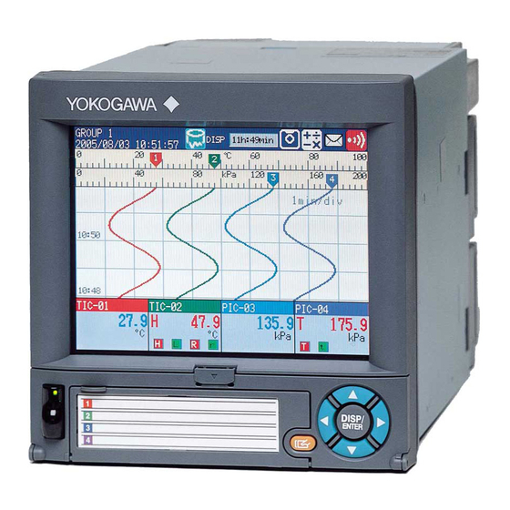
Names of Parts
Front View Component Identification
Identifies parts on the front view: LCD, indicators, keys, USB, and CF card slot.
Key Panel and Key Functions
Details the operation of keys, soft keys, and the key panel cover.
Names of Parts (Continued)
Rear Panel Connections
Identifies rear panel ports: USB, Ethernet, Serial, and Optional terminals.
Desktop Type (/H5[] Option) Features
Details specific features of the desktop model, including handle and connectors.
DX1000/DX1000N Workflow
Installation Steps
Guides through the initial installation process of the DX.
Wiring Steps
Details on connecting input/output wires and the power cord.
Power ON Procedure
Step-by-step instructions for turning the DX power on.
Environmental Settings Configuration
Guides on setting date/time and loading the CF card.
Functional Settings Configuration
Instructions for configuring measurement functions.
Measurement and Data Saving Steps
Covers starting measurement, screen operations, and saving data.
Data Management Using DAQSTANDARD
Steps for checking, managing, and converting measured data.
Turning Power ON/OFF
Procedure for Turning Power ON
Step-by-step guide for powering on the DX, including safety cautions.
Procedure for Turning Power OFF
Step-by-step guide for powering off the DX, including safety cautions.
Basic Operation
Panel Keys and Display Overview
Identifies the LCD and various keys on the DX control panel.
Soft Key Functionality
Explains how soft keys select menu items at the bottom of the screen.
Navigation and Selection Keys
Describes the function of the DISP/ENTER and arrow keys.
Key Functions: Start/Stop, User, ESC, Menu
Details the primary functions of the START/STOP, USER, ESC, and MENU keys.
Favorite and FUNC Key Functions
Explains how Favorite key displays screens and FUNC key accesses menus.
Status Display Section Details
Status Display Section Elements
Describes the display name, date/time, recording, and alarm icons.
Data Display Section Elements
Shows measured data and functional setup information.
Memory Sample Status Indicators
Details memory sample progress, stopped status, and remaining time indicators.
Status Icon Meanings
Explains icons for alarms, status, computation, and CF card access.
Run Modes
Description of Operation Modes
Defines the Operation, Setting, and Basic Setting modes.
Mode Transition Diagram
Illustrates how to switch between the different operating modes.
Entering Values and Characters
Character/Number Input Window
Describes the window used for inputting various data types.
Navigation and Selection Keys
Explains the use of DISP/ENTER and arrow keys for input.
Input Window Control Keys
Details the functionality of cursor movement, Ins, Del, ENT, and Bs keys.
Character Type Selection
Explains how the A/a/1 key changes the character input type.
Changing the Date/Time
Step 1: Display Operation Screen
Initial action to view the main operation screen.
Step 2: Access Setting Menu
Presses the MENU key to open the main setting menu.
Step 3: Select Date/Time Option
Navigates to the Date/Time settings within the menu.
Step 4: Open Time Set Window and Change Date
Opens the time window and demonstrates changing the date value.
Step 5: Return to Operation Mode
Exits settings and returns to the main display screen.
Changing Input Range (Setting Mode)
Example: Thermocouple Type T (0.0-400.0°C)
Sets channel 2 to Type T thermocouple with a specific range.
Display Operation Screen
Initial step to access the device's main display.
Access Setting Menu and Select Channel
Navigates through menus to reach channel measurement settings.
Select Range and Alarm Settings
Accesses the specific configuration options for range and alarms.
Set First Channel and Move Cursor to Mode
Specifies the starting channel and navigates to the mode selection.
Changing Input Range (Setting Mode) - Continued
Select Thermocouple (TC) Type
Selects the specific thermocouple type (e.g., Type T).
Navigate to Span Settings
Uses soft keys to move to the Span Lower and Span Upper settings.
Enter Span Lower and Upper Values
Inputting the lower (0.0) and upper (400.0) range limits.
Confirm and Apply Settings
Uses DISP/ENTER to save changes and return to the previous screen.
Changing Scan Interval (Basic Setting Mode)
Example: Setting Scan Interval to 2 Seconds
Demonstrates changing the scan interval for data acquisition.
Display Operation Screen and Access Setting Menu
Initial steps to reach the main setting menu.
Switch to Basic Setting Mode
Uses FUNC key to transition to the basic setting configuration.
Navigate to A/D, Memory Settings
Selects the A/D and Memory configuration section.
Changing Scan Interval (Basic Setting Mode) - Continued
Set Scan Interval to 2 Seconds
Selects the '2s' option for the scan interval.
Confirm and Save Scan Interval Setting
Saves the changed scan interval and returns to the basic setting menu.
Navigate to End Option and Confirm Save
Selects 'End' to save all changes and confirm the operation.
Inserting and Removing CF Card
Procedure for Inserting a CF Card
Step-by-step guide to insert the CF card into the device.
CAUTION: CF Card Insertion
Warning about inserting the CF card upside down to prevent damage.
Procedure for Removing a CF Card
Step-by-step guide for safely removing the CF card.
Media Ejection (Operation Mode)
Details on ejecting the CF card using the operation mode menus.
Inserting and Removing CF Card (Continued)
Media Ejection (Basic Setting Mode)
Details on ejecting the CF card using the basic setting mode menus.
Note: CF Card Removal Warning
Warns about consequences of removing CF card without proper ejection.
Saving Setup Data
Access Settings and Select Save/Load
Navigates through menus to reach the save/load functions.
Select Save Settings Option
Chooses the option to save the current configuration.
Enter File Name and Save Data
Inputting a file name and confirming the save operation.
Loading Setup Data
Access Settings and Select Save/Load
Navigates through menus to reach the save/load functions.
Select Load Settings Option
Chooses the option to load a previously saved configuration.
Select Setup File and Load Data
Chooses the setup file and initiates the data loading process.
Setting Input Range and Alarm
Example 1: Temperature Measurement Channel
Guides through setting up a temperature measurement channel.
Input Range Configuration
Sets the input range for a measurement channel.
Tag Configuration
Sets the tag identifier for the measurement channel.
Setting Input Range and Alarm (Continued)
Example 2: Flow Rate Channel and Alarm
Guides through setting up a flow rate channel with an alarm condition.
Input Range and Alarm Configuration
Sets the input range and alarm condition for the channel.
Tag Configuration
Sets the tag identifier for the measurement channel.
Setting the Display
Example 3: Assigning Channels to Groups
Demonstrates how to group channels for display purposes.
Group Configuration
Sets up channel assignments within display groups.
Setting the Display (Continued)
Example 4: Setting the Time Scale
Adjusts the time scale (per division) for trend waveforms.
Trend Interval Configuration
Sets the trend interval, which determines time per division on the graph.
Setting the Data Storage
Example 5: Continuous Record and Auto Save
Configures continuous data recording and automatic saving to CF card.
Data to be Recorded Configuration
Specifies which data to record and how it should be handled.
CF Card Storage Method (Auto Save)
Enables or disables the automatic saving of data to the CF card.
Setting the Data Storage (Continued)
Saving Settings Procedure
Steps to save the configured data storage settings.
Channels to be Recorded Configuration
Specifies which measurement channels are included in the recording.
CF Card Save Interval Configuration
Sets the interval at which data is saved to the CF card.
Data File Name Configuration
Defines the naming convention for the saved data files.
Save Destination Directory Configuration
Specifies the folder on the CF card where data will be saved.
Setting the Data Storage (Continued)
Example 6: Save Data at Specified Time
Configures data saving to occur daily at a specific time.
Setting the Time for Data Saving
Configures the specific time when data saving should occur.
Specifying Data Storage Action
Links the time event to the data storage action.
Customizing the Operation
Example 7: Assign Screen Image Save to USER Key
Assigns the screen image capture function to the USER key.
Assigning Action to USER Key
Configures the action performed when the USER key is pressed.
Customizing the Operation (Continued)
Example 8: Register Screens to Favorite Key
Allows registering frequently used screens for quick access.
Register Trend Screen to Favorite Key
Demonstrates registering a historical trend screen.
Display Screen for Registration
Shows the screen that needs to be registered.
Access FUNC Key Menu and Navigate
Guides through accessing menus to reach favorite registration.
Display Registration List Window
Opens the window showing registered favorite screens.
Customizing the Operation (Continued)
Select Favorite Number Slot
Chooses a slot (1-8) for registering a favorite screen.
Press Regist Soft Key
Initiates the registration process for the selected favorite slot.
Enter Display Name for Registered Screen
Inputting a custom name for the saved screen.
Register Multiple Screens
Instructions for repeating the process to register up to eight screens.
Operation
Starting the Memory Sample
Steps to initiate the data recording process using the START key.
Stopping the Memory Sample
Steps to stop the data recording process using the STOP key.
Confirming Stop Action
Displays a confirmation window and selects the stop method.
Switching Display Types
Access Display Selection Menu
Presses DISP/ENTER to show the menu for changing display types.
Select Display Type and Group
Chooses display type (TREND, DIGITAL, BAR) and group number.
Apply Selected Display and Group
Presses DISP/ENTER to show the chosen display and group.
Switching Display Order and Group
Explains how to cycle through displays and groups using arrow keys.
Writing Messages
Registering Message Number 1 "START"
Guides through registering the word 'START' as message number 1.
Access Message Settings and Input Window
Navigates to message settings and activates the input window.
Input Message Text and Confirm
Enters message text using the keypad and confirms the input.
Writing Messages (Continued)
Message Writing During Operation
Notes that messages can be written while memory sample is in progress.
Access Message Registration Menu
Guides through accessing the message registration interface.
Select Message Slot and Display on Trend
Selects a message slot and shows how the message appears on the trend display.
Connecting to Ethernet Network
Example 9: Monitoring DX via PC Browser
Guides on monitoring the DX screen using a PC browser over Ethernet.
DX and PC Ethernet Setup Items
Lists required IP address and subnet mask settings for DX and PC.
DX IP Address Configuration
Steps to configure the DX's IP address using basic setting mode.
Connecting to Ethernet Network (Continued)
Enable DX Web Server Function
Activates the web server function for browser access.
Display DX Screen on PC via Browser
Accesses the DX's interface through a web browser.
Save Ethernet Configuration Settings
Procedure for saving the configured network settings.
Setting the PC Network Configuration
Configures IP address and subnet mask on the PC.
Connecting to Ethernet Network (Continued)
Check Network Connection via Ping
Verifies network connectivity by sending a ping command.
Display DX Screen in Web Browser
Accesses and views the DX's interface using a web browser.
Enter DX URL in Browser
Inputting the specific web address to access the DX.
Connecting to Ethernet Network (Continued)
Example 10: Automatic Data Transfer to FTP Server
Configures automatic transfer of measured data files to an FTP server.
DX Setup Items for FTP Transfer
Details host name, IP address, and data type settings for FTP.
FTP Server Configuration
Provides parameters like server name, port, login name, and password.
DX IP Address and Host Settings
Configures DX IP address and host settings for network access.
Using DAQSTANDARD Software
Display Measured Data with DAQSTANDARD
Guides on using DAQSTANDARD to view measured data files.
Load Data File into PC
Inserts CF card and starts DAQSTANDARD to load data.
Launch Data Viewer and Open File
Opens the data viewer and selects the desired data file for display.
Installation and Wiring
Installation Location Guidelines
Recommendations for choosing a suitable installation environment.
Prohibited Installation Locations
Lists environments where the DX should not be installed.
Panel Mount Installation Procedure
Detailed steps for mounting the DX into an instrumentation panel.
Desktop Type (/H5[]) Installation Precautions
Specific handling and installation advice for the desktop model.
Installation and Wiring (Continued)
General Wiring Procedure
Basic steps for connecting signal wires to the DX terminals.
Input Terminals Arrangement Diagrams
Illustrations showing terminal layouts for different DX models.
Installation and Wiring (Continued)
External Dimensions and Panel Cut Dimensions
Provides physical dimensions and panel cutout sizes for mounting.
Installation and Wiring (Continued)
Input Signal Wiring Precautions
Covers warnings, cautions, and general precautions for wiring input signals.
Noise Prevention Techniques for Wiring
Methods to minimize noise from power cables and electromagnetic induction.
Parallel Connection Precautions
Advice on connecting input wires in parallel to avoid signal degradation.
Installation and Wiring (Continued)
Wiring Screw Terminals
Wiring diagrams for DC voltage, RTD, TC, and DC current inputs.
Wiring Clamped Terminals Procedure
Steps and recommendations for wiring clamped terminals.
Installation and Wiring (Continued)
Wiring Screw Terminals Diagrams
Illustrates wiring for various screw terminal inputs.
Wiring Clamped Terminals Details
Provides procedure, tool usage, and wire recommendations for clamped terminals.
Installation and Wiring (Continued)
Optional Terminal Wiring
Covers precautions and procedures for wiring optional terminals.
WARNING: High Voltage Wiring Precautions
Safety warnings for wiring output terminals with high voltages.
CAUTION: Output Terminal Voltage Limits
Cautions regarding voltage limits for output terminals and transmitter power supply.
Installation and Wiring (Continued)
Optional Terminals Arrangement Diagrams
Illustrates terminal layouts for optional connections like alarm, remote control, etc.
Installation and Wiring (Continued)
Connecting to RS-422A/485 Interface (/C3)
Wiring instructions for the RS-422A/485 serial communication.
Connecting to USB Port (/USB1)
Information on connecting the device via the USB interface.
Connecting to Ethernet Port
Details on connecting the device to an Ethernet network.
Checking Ethernet Connection Status
Methods to verify Ethernet connection status via indicator and display.
Installation and Wiring (Continued)
Power Supply Wiring (Panel Mount Type)
Precautions and procedure for wiring the power supply on panel mount models.
Power Supply Specifications Table
Lists required power supply voltage, frequency, and consumption.
Installation and Wiring (Continued)
Power Supply Wiring (Desktop Type (/H5[] Option))
Precautions and procedure for connecting power to desktop models.
Power Supply Specifications Table
Lists required power supply voltage, frequency, and consumption.
Recommended Replacement Periods for Worn Parts
Parts Replacement Period Table
Lists parts like LCD, battery, and assemblies with their recommended replacement periods.
Notes on Replacement Periods
Clarifies factors affecting replacement periods, like temperature and usage.
Note on LCD Brightness and Color
Explains LCD half-life, brightness impact, and potential color changes.
Setup Items and Default Values
Setting Mode Menu Overview
Lists setup items accessible in the setting mode and their page references.
Basic Setting Mode Menu Overview
Lists setup items accessible in basic setting mode and their page references.
Setup Items and Default Values (Continued)
Date/Time Settings Defaults
Default values for Date & Time and Daylight Saving Time settings.
Meas Channel Range/Alarm Defaults
Default values for channel range and alarm configuration.
Setup Items and Default Values (Continued)
Channel Mode Settings Defaults
Default values for Volt, TC, RTD, Scale, Delta, and DI channel modes.
Setup Items and Default Values (Continued)
Channel Mode Settings Defaults (1-5V, Sqrt)
Default values for 1-5V and Sqrt channel modes.
Alarm and Tag/Memory/Delay Defaults
Default values for Alarm, Tag, Memory, and Delay settings.
Moving Average, Color, Zone/Scale Defaults
Default values for Moving Average, Color, Zone, and Scale settings.
Setup Items and Default Values (Continued)
Bar Graph, Partial, Alarm Mark Defaults
Default values for Bar Graph, Partial display, and Alarm Mark settings.
Color Scale Band and Calibration Correction Defaults
Default values for Color Scale Band and Calibration Correction settings.
Setup Items and Default Values (Continued)
Math Channel Settings Defaults (Part 1)
Defaults for Expression, Constant, Tag/Memory/Delay, TLOG/Rolling Avg.
Math Channel Settings Defaults (Part 2)
Defaults for Color, Zone, Scale, and Bar Graph settings.
Setup Items and Default Values (Continued)
Math Channel Settings Defaults (Part 3)
Defaults for Partial, Alarm Mark, Color Scale Band, Math Start Action.
Setup Items and Default Values (Continued)
Display Settings Defaults
Defaults for Trend, Bar Graph, LCD, and Monitor display settings.
Group Set, Trip Line, and Message Defaults
Defaults for Group, Trip Line, and Message configurations.
Setup Items and Default Values (Continued)
Timer and Event Action Settings Defaults
Defaults for Timer, Match Time Timer, and Event Action settings.
Setup Items and Default Values (Continued)
Basic Setting Mode Setup Items Defaults
Defaults for Alarm, Hysteresis, A/D, Memory, Burnout, RJC.
Environment Settings Defaults (Part 1)
Defaults for Operating Environment, View, Message, Input, Alarm.
Setup Items and Default Values (Continued)
Environment Settings Defaults (Part 2)
Defaults for Security, Media Save, Batch, Service Port, Math, Report.
Keylock Settings Defaults
Defaults for Keylock settings and key action assignments.
Setup Items and Default Values (Continued)
Login and User Settings Defaults
Defaults for Login, Basic, Admin, User settings, and Authority.
Report, Time Settings, Load/Initialize Defaults
Defaults for Report, Time settings, Load settings, Initialize, and Media eject.
Setup Items and Default Values (Continued)
Ethernet Communication Settings Defaults (Part 1)
Defaults for IP Address, Host, DNS, Keep Alive, Server, Web Page.
Setup Items and Default Values (Continued)
Ethernet Communication Settings Defaults (Part 2)
Defaults for E-Mail settings (Basic, Alarm, Scheduled, System, Report).
Setup Items and Default Values (Continued)
Ethernet Communication Settings Defaults (Part 3)
Defaults for FTP Client, SNTP Client, and Modbus Client settings.
Setup Items and Default Values (Continued)
Serial Communication Settings Defaults
Defaults for Serial communication (Basic, Modbus Master, Status Relay).
Need help?
Do you have a question about the DX1002 and is the answer not in the manual?
Questions and answers