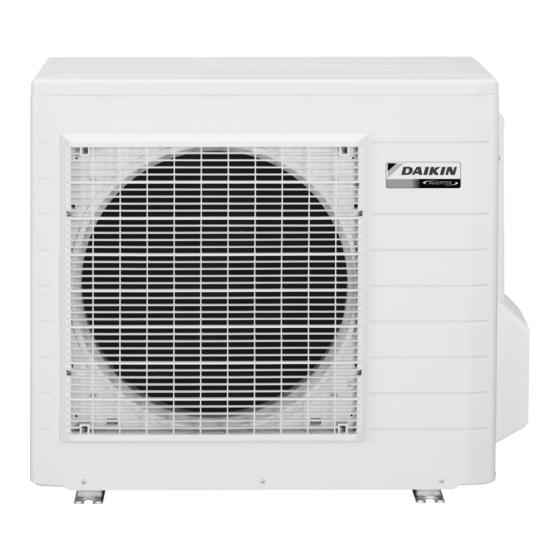
Summarization of Contents
Removal of Outer Panels
Remove Top Panel
Procedure to remove the top panel by unscrewing it and lifting.
Remove Discharge Grille
Procedure to detach the discharge grille by removing screws and unfastening hooks.
Remove Front Panel
Steps to remove the front panel by unscrewing and unfastening hooks.
Remove Stop Valve Cover
Procedure to remove the stop valve cover by removing screws and unfastening hooks.
Removal of Outdoor Fan and Fan Motor
Remove Electrical Box Cover
Procedure to remove the electrical box cover after removing the shield plate.
Disconnect Fan Motor Connector
Procedure to disconnect the fan motor electrical connector.
Release Fan Motor Lead Wire
Procedure to release the fan motor lead wire from hooks.
Remove Outdoor Fan Securing Nut
Procedure to remove the nut securing the outdoor fan.
Remove Fan Motor Screws
Procedure to remove lower and upper screws from the fan motor.
Extract Fan Motor
Procedure to release fan motor lead wire and pull out the fan motor.
Removal of Electrical Box
Remove Shield Plate
Procedure to remove the shield plate by unscrewing and unfastening hooks.
Disconnect Power and Earth Wires
Procedure to disconnect power supply, connection, and earth wires.
Remove Right Side Panel
Procedure to remove the right side panel by unscrewing and unfastening hooks.
Disconnect Internal Connectors and Wires
Procedure to disconnect various electrical connectors and release wires from clamps.
Remove Electrical Box Assembly
Procedure to remove the electrical box by unscrewing and releasing wires.
Removal of PCBs
Remove Service Monitor PCB
Procedure to disconnect connectors, release clamps, and remove service monitor PCB.
Disconnect Terminal Board Harnesses
Procedure to unfasten hooks, open terminal board, and disconnect various connectors.
Remove Main PCB
Procedure to remove the main PCB by unscrewing and unfastening hooks.
Removal of Sound Blankets and Thermistors
Remove Top and Back Sound Blankets
Procedure to remove sound blankets from the top and back of the unit.
Remove Outer and Inner Sound Blankets
Procedure to remove outer and inner sound blankets from the unit.
Release and Remove Thermistors
Procedure to release discharge pipe and heat exchanger thermistors.
Removal of Four Way Valve
Remove Four Way Valve Coil
Procedure to remove the four way valve coil by unscrewing it.
Disconnect Four Way Valve Brazed Parts
Procedure to heat and disconnect the brazed parts of the four way valve.
Removal of Electronic Expansion Valve
Remove Expansion Valve Coil
Procedure to pull out the electronic expansion valve coil.
Disconnect Electronic Expansion Valve
Procedure to remove putty and heat/disconnect the electronic expansion valve.
Removal of Compressor
Remove Terminal Cover and Disconnect Wires
Procedure to remove the terminal cover and disconnect compressor lead wires.
Release Clamp and Remove Putty
Procedure to release compressor lead wires from clamp and remove putty.
Remove Compressor Nuts
Procedure to remove the two nuts securing the compressor.
Disconnect Compressor Brazed Parts
Procedure to heat and disconnect the brazed parts of the compressor.
Lift and Remove Compressor
Procedure to lift and remove the compressor from the unit.


Need help?
Do you have a question about the RXS60FVMA and is the answer not in the manual?
Questions and answers