
Related Manuals for ModMAG M2000


Summary of Contents for ModMAG M2000
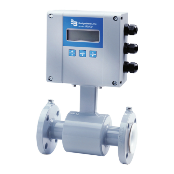
- Page 1 M-Series® M2000 Electromagnetic Flow Meter User Manual MAG-UM-01272-EN-07 (October 2018)
- Page 2 M-Series® M2000, Electromagnetic Flow Meter Page ii MAG-UM-01272-EN-07 October 2018...
-
Page 3: Table Of Contents
User Manual CONTENTS Safety Precautions and Instructions . . . . . . . . . . . . . . . . . . . . . . . . . . . . . . . . . . . . . . . . . . . . . . . . . . . . . . . . . . . 5 System Description . - Page 4 M-Series® M2000, Electromagnetic Flow Meter Mount Bracket to Amplifier . . . . . . . . . . . . . . . . . . . . . . . . . . . . . . . . . . . . . . . . . . . . . . . . . . . . . . . . . .15 Wiring Configuration .
-
Page 5: Safety Precautions And Instructions
. SYSTEM DESCRIPTION The Badger Meter M-Series® model M2000 electromagnetic flow meter is intended for fluid metering in most industries including water, wastewater, food and beverage, pharmaceutical and chemical . The basic components of an electromagnetic flow meter are: The detector, which includes the flow tube, isolating liner and measuring electrodes . -
Page 6: Unpacking And Inspection
Unpacking and Inspection UNPACKING AND INSPECTION Follow these guidelines when unpacking the M-Series equipment . • If a shipping container shows any sign of damage, have the shipper present when you unpack the meter . • Follow all unpacking, lifting and moving instructions associated with the shipping container . - Page 7 Unpacking and Inspection • Use the sling-rigged method to lift large detectors into a vertical position while they are still crated . Use this method to position while they are still crated . Use this method to position large detectors vertically into pipelines . Figure 3: Sling-Rigged lifting methods •...
-
Page 8: Meter Location, Orientation And Applications
Meter Location, Orientation and Applications METER LOCATION, ORIENTATION AND APPLICATIONS The M2000 provides two amplifier mounting options: a meter mount option and a remote mount option . Meter mount Remote mount Figure 5: Amplifier mounting options Temperature Ranges TO PREVENT DAMAGE TO THE METER, STRICTLY OBSERVE THE AMPLIFIER’S AND DETECTOR’S MAXIMUM TEMPERATURE RANGES. -
Page 9: Meter Orientation
Meter Location, Orientation and Applications Meter Orientation Mag meters can operate accurately in any pipeline orientation and can measure volumetric flow in forward and reverse directions as long as the pipe is completely full . OTEE: A "Forward Flow" direction arrow is printed on the detector label . Vertical Placement Mag meters perform best when placed vertically, with liquid flowing upward and meter electrodes in a closed, full pipe . -
Page 10: Pipe Reducer Requirements
Meter Location, Orientation and Applications Pipe Reducer Requirements With pipe reducers, a smaller meter can be mounted in larger pipelines . This arrangement may increase low-flow accuracy . There are no special requirements for standard, concentric, pipe reducers . Custom fabricated pipe reducers must have an approximate slope angle of 15 degrees to minimize flow disturbances and excessive loss of head . -
Page 11: Partially-Filled Pipe Situations
Meter Location, Orientation and Applications Partially-Filled Pipe Situations In some locations, the process pipe may be momentarily only partially filled . Examples include: lack of back pressure, insufficient line pressure and gravity flow applications . To eliminate these situations: • Do not install the meter at the highest point of the pipeline . -
Page 12: Meter Gaskets And Grounding
Meter Gaskets and Grounding METER GASKETS AND GROUNDING Gasket and grounding requirements must be considered when determining the meter location, orientation and application . Meter/Pipeline Connection Gaskets You must install gaskets (not provided) between the detector's isolating liner and the pipeline flange to ensure a proper and secure hydraulic seal . -
Page 13: Non-Conductive Pipe Grounding
Amplifier Mounting Configuration Options Non-Conductive Pipe Grounding MPORTANT If the process pipe is not electrically conductive (PVC, fiberglass, cement-lined pipes or any other non-conductive material) and the meter was not originally ordered with an optional grounding electrode, you must install a pair of grounding rings between the mating flanges at both ends of the meter. -
Page 14: Wiring
Wiring WIRING Wiring Safety AT INSTALLATION, BE SURE TO COMPLY WITH THE FOLLOWING REQUIREMENTS: • Disconnect power to the unit before attempting any connection or service to the unit . • Do not bundle or route signal lines with power lines . •... -
Page 15: Power Connections
Wiring Power Connections External Disconnect • Install an external disconnect switch or circuit breaker that meets local standards . • Position the M2000 in an accessible location . • Position and identify the disconnect device so as to provide safe and easy operation . •... -
Page 16: Wiring For Remote Configuration
Wiring Wiring for Remote Configuration shield (black) green yellow pink CS C2 C1 shield (black) brown shield (black) white white shield (black) brown shield (black) pink yellow shield (black) green Figure 17: Wiring for remote configuration Remote style M2000 amplifier models can be ordered with standard cables measuring 15, 30, 50,100 and 150 feet . In addition, cables up to 500 feet are available . -
Page 17: Configuring Input/Output (I/O)
Configuring Input/Output (I/O) CONFIGURING INPUT/OUTPUT (I/O) This section describes wiring the following M2000 inputs/outputs: • Analog output • Digital input • Digital outputs • Communication Once the sensor and the amplifier have been wired, wire any inputs and outputs to the M2000 amplifier . Do not connect the main power connection until you have made all other wiring connections . -
Page 18: Analog Output Wiring Diagram
Configuring Input/Output (I/O) Input/Output Description Terminal Analog Output 0…20 mA Resistive Load < 800 ohms 16 (+) 4…20 mA Resistive Load < 800 ohms 15 (–) 0…10 mA Resistive Load < 800 ohms 2…10 mA Resistive Load < 800 ohms Digital Output 1 Passive max . -
Page 19: Digital Output Wiring Diagrams
Configuring Input/Output (I/O) Digital Output Wiring Diagrams Digital Input Wiring Diagram October 2018 MAG-UM-01272-EN-07 Page 19... -
Page 20: Programming The M2000
Programming the M2000 PROGRAMMING THE M2000 The M2000 amplifier comes pre-programmed from the factory . Typically, you will not need to do any additional programming . However, to take advantage of special features, you can program the meter for your specific needs . If you will be programming the meter, familiarize yourself with the M2000 Function Buttons and follow the procedures outlined below . -
Page 21: Function Buttons
Programming the M2000 OTEE: The bottom line of a numeric-value display provides prompts regarding the function of each button . The [+] or [–] button will change the value of the numeral . The [E] button will move the cursor one digit to the right . When the cursor is at the final, right-most digit, pressing [E] will reposition the cursor at the left-most digit . - Page 22 Programming the M2000 Consider the Down Arrow [ – | ↓ ] button as the "previous step" button . During a procedure, pressing this button will go to the menu's previous selection or decrement a numeral . Example 1E: The illustration below shows the M2000 Main Menu . The selection arrow is pointing to the Meter Setup selection . To scroll the text down to the menu's previous selection, Exit this Menu (which is not visible on the display), press [↓] once .
-
Page 23: Security
Security SECURITY The M2000 security feature gives you the option to restrict access to the meter by way of a five-digit Personal Identification Number (PIN) . The system administrator can set up a single PIN for each of the three different levels of access: •... -
Page 24: Entering Your Personal Identification Number (Pin)
Security Entering Your Personal Identification Number (PIN) If your system has been set up with PIN security, you need to enter a PIN to access programming functions . There are three access levels, each with its own unique PIN: User, Service and Administration . Your system administrator will provide you with the appropriate PIN . -
Page 25: Setting Up The M2000 With Quick Setup
Setting Up the M2000 with Quick Setup SETTING UP THE M2000 WITH QUICK SETUP The M2000 provides you with a Quick Setup utility that allows you to set or change your Flow Units, Totalizer Units, Full Scale Flow and Low Flow Cutoff settings . To open the Quick Setup, select Quick Setup from the Start Menu . Quick Setup Flow Unit Flow Unit lets you set the unit of measure for the flow rate and full scale flow . - Page 26 Setting Up the M2000 with Quick Setup Quick Setup Full Scale Flow Full Scale Flow sets the maximum flow the system is expected to measure . This parameter has influence on other system parameters . These parameters include: • Frequency Output – Full scale frequency is observed at full scale flow •...
-
Page 27: Quick Reference
Quick Reference QUICK REFERENCE Main Menu Meter Setup Scale Factor Empty Pipe Detect Power Line Freq Excitation Freq Pipe Diameter Detector Factor Detector Offset Measurements Velocity Unit Flow Unit Totalizer Unit Full Scale Flow Low Flow Cutoff Flow Direction Damping Factor Inputs/Outputs Analog Output Digital Input... -
Page 28: Using The M2000 Main Menu Programming Options
Using the M2000 Main Menu Programming Options USING THE M2000 MAIN MENU PROGRAMMING OPTIONS The following M2000 programming options are available from the Main Menu: • Meter Setup • Measurements • Inputs/Outputs • Clear Totals • Communications • Advanced • Info/Help •... - Page 29 Using the M2000 Main Menu Programming Options Meter Setup Excitation Freq The Excitation Freq parameter is set at the factory . You can change Excitation Freq to configure the DC excitation of the coils . Supported frequencies are dependent on the configured power line frequency: [Factory Set] 50 Hz 60 Hz...
- Page 30 Using the M2000 Main Menu Programming Options Measurements Velocity Unit Velocity Unit lets you set the velocity to meters/sec or feet/sec . [ft/sec] To set Velocity Unit, follow these steps from the Measurements menu: 1 . Select Velocity Unit . ...
- Page 31 Using the M2000 Main Menu Programming Options Measurements Full Scale Flow The Full Scale Flow parameter sets the maximum flow the system is expected to measure . This parameter has influence on other system parameters . These parameters include: [Factory Set] •...
- Page 32 Using the M2000 Main Menu Programming Options Measurements Damping Factor The damping factor establishes the stability of the measured flow rate . If back and forth oscillations of the flow rate are observed during normal flow conditions, increase this value incrementally until the [No Damping] flow rate stabilizes .
- Page 33 Using the M2000 Main Menu Programming Options Inputs/Outputs Digital Input Digital Input lets you configure the functional operation of the digital input . The following functions are supported: • Remote Reset – Clears totalizer T2 (uni-directional) • Batch Reset – Resets batch totalizer PS to preset amount and clears T2 (uni-directional) •...
- Page 34 Using the M2000 Main Menu Programming Options Inputs/Outputs Digital Output Pulses/Unit The Pulses/Unit parameter lets you set how many pulses per unit of measure will be transmitted to remote applications . For example, assuming the unit of measure is gallons: •...
- Page 35 Using the M2000 Main Menu Programming Options Inputs/Outputs Digital Output Preset Amount Preset amount lets you set the reset value for the associated PS totalizer when the (continued) digital input is set to Batch Reset . [0 .0] To change the preset amount, follow these steps from the Inputs/Outputs menu: 1 .
- Page 36 Using the M2000 Main Menu Programming Options Inputs/Outputs Digital Output (continued) Hardware Type The Hardware Type parameter lets you select the type of hardware used to drive the output signal: either open collector or solid-state relay . [3: Open Collector] To change the Hardware Type, follow these steps from the Inputs/Outputs [4: Open Collector] main menu:...
- Page 37 Using the M2000 Main Menu Programming Options Clear Totals The bi-directional net totalizer, when reset, clears both the forward and the reverse flow totalizers (T+ and T–) . This is reset within the menu manager or through remote communications . Clearing TN also clears the associated rollover counter .
- Page 38 Using the M2000 Main Menu Programming Options Communication Port A Port Address This parameter establishes the MODBUS RTU address . MODBUS RTU requests will only Settings be processed if the configured port address of the meter matches the request address (continued) found in the MODBUS RTU packet .
- Page 39 Using the M2000 Main Menu Programming Options Communication Port B OTEE: The parameters for Port B are the same as for Port A, with the exception of the additional Settings External Port Address detailed below . Port Address An additional communication port, known as Port B, is used to offer enhanced communications with the meter .
- Page 40 The Data Logger feature requires firmware version 1 .10 or later . Reference Badger Meter P/N 67354-003 to obtain a firmware upgrade kit . See the M-Series M2000 Data Logging user manual, available at www.badgermeter.com, for details on this feature .
- Page 41 Using the M2000 Main Menu Programming Options Advanced Backlight Control You can set the meter's backlight to: Always On, Always Off and Timed Off . [Timed Off ] When set to Timed Off, the backlight will automatically turn off after one minute of inactivity (no buttons pressed) .
- Page 42 Using the M2000 Main Menu Programming Options Advanced Software Filter Description The software filter operates as an acceleration filter . This filter, when configured ACC-Filter properly, allows for filtering of fast changes in fluid flow . Generally, this filter is used in applications having highly conductive fluids .
- Page 43 Using the M2000 Main Menu Programming Options Advanced Software Filter Peak Detect Peak Detect offers a diagnostic view of the acceleration components observed ACC-Filter during flow conditions . This parameter records the “high water mark” of the [0 M /Sec (continued) measured accelerations component .
- Page 44 Using the M2000 Main Menu Programming Options Advanced Empty Pipe Cal. Fluid conductivity impacts the performance of empty pipe measurements . If you require empty pipe detection, you should perform this empty pipe calibration procedure . [Default] Before starting the empty pipe calibration, verify that empty pipe detection is enabled . Also, run both the empty pipe and the full pipe calibration procedures .
- Page 45 Using the M2000 Main Menu Programming Options Advanced Security Set Admin PIN Users logged in with this PIN will have access to all M2000 procedures . [00000] To set the administrator's PIN, follow these steps from the Advanced Menu: 1 . Select Security to view the Security menu . 2 .
- Page 46 Using the M2000 Main Menu Programming Options Info/Help Error Counts Description This menu provides a diagnostic view of the meter’s performance . Below are several system diagnostic counters and their definitions . Use discretion when interpreting these counters . These values could be altered during system setup or when using the verification device .
- Page 47 Encoder Protocol Interface Info/Help Restore Defaults Restores all non-calibrated parameters to the factory defaults . [Not applicable] Language Select Language Select The M2000 supports one alternate language along with English . This alternate language choice is set at the factory . The options are: Spanish, German, Czech or French . [English] To select the language, follow these steps from the Language Select menu: 1 .
-
Page 48: Encoder Protocol Interface
Encoder Protocol Interface ENCODER PROTOCOL INTERFACE This feature requires firmware version 1 .10 or later . Reference Badger Meter P/N 67354-003 to obtain a firmware upgrade kit . Enabling the meter as an encoder requires three settings, all within the advanced menu, to be configured . •... - Page 49 Encoder Protocol Interface The following table demonstrates how the totalizers are displayed under various configurations of the Totalizer Resolution (that is, resolution) and Dial Type . The non-shaded digits are transmitted as defined by the dial type . For example, if the dial type is 4-dial and the resolution is 10000 then an arbitrary totalizer value of 99999999 is displayed on the meter as 99990000 and 9999 is transmitted to the receiving application .
-
Page 50: Store / Restore Feature
Store / Restore Feature Dial Totalizer Display Digits Type Resolution 10000 Not Applicable– Not enough display digits 1000 Not Applicable– Not enough display digits Not Applicable– Not enough display digits 9 dial 0 .1 0 .01 0 .001 0 .0001 10000 Not Applicable–... -
Page 51: Maintenance
SHOCK. REPLACE THE FUSE ONLY WITH 250V AC, 2 AMP, SLOW BLOW (5 X 20 MM). AUTHORIZED PERSONNEL MUST REPLACE FUSES. Replacing the Circuit Board Refer to the M-Series M2000 Interchangeability Procedure Application Brief for information on replacing circuit boards . October 2018 MAG-UM-01272-EN-07... -
Page 52: Troubleshooting
Troubleshooting TROUBLESHOOTING The M2000 mag meter is designed for many years of optimal performance . However, should it malfunction, there are certain things that we recommend you check before contacting our Technical Support department or your local Badger Meter Representative . OTEE: If the fluid measured has a high concentration of conductive solids, deposits may accumulate on the internal liner walls and electrodes . - Page 53 Troubleshooting Menu Manager Configuration Errors Error Description Recommended Action ADEE: Configuration of the ADE This error is displayed when an invalid modification to either of the following menu parameters is detected: Protocol Type, Dial Type, Totalizer Resolution, Digital Input Function Type or Digital Output interface is invalid.
- Page 54 Troubleshooting Menu Manager Configuration Errors Error Description Recommended Action Output 1/2E: Output Type This error is observed when the function type is ADE and the output type is changed from Normally Configuration Error Open to Normally Closed . It is required for ADE operation that the output type be Normally Open . Full Scale FlowE: Entered Value Value entered exceeds the absolute maximum flow the meter supports .
-
Page 55: Specifications
Specifications SPECIFICATIONS Flow Range 0 .10…39 .4 ft/s (0 .03…12 m/s) Accuracy ± 0 .25 percent of rate for velocities greater than 1 .64 ft/s (0 .50 m/s) ± 0 .004 ft/s (± 1 mm/s) for velocities less than 1 .64 ft/s (0 .50 m/s) Repeatability ±... - Page 56 Control. Manage. Optimize. M-SERIES is registered trademark of Badger Meter, Inc . Other trademarks appearing in this document are the property of their respective entities . Due to continuous research, product improvements and enhancements, Badger Meter reserves the right to change product or system specifications without notice, except to the extent an outstanding contractual obligation exists .
Need help?
Do you have a question about the M2000 and is the answer not in the manual?
Questions and answers