
Related Manuals for ModMAG M1000


Summary of Contents for ModMAG M1000
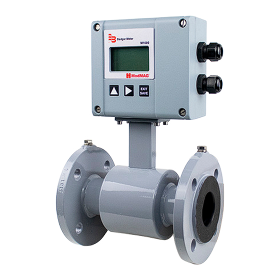
- Page 1 ModMAG® M1000 Electromagnetic Flow Meter User Manual MAG-UM-00379-EN-07 (March 2020)
-
Page 2: Table Of Contents
ModMAG® M1000 Electromagnetic Flow Meter CONTENTS Safety Precautions and Instructions . . . . . . . . . . . . . . . . . . . . . . . . . . . . . . . . . . . . . . . . . . . . . . . . . . . . . . . . . . . 5 Basic Precautions . - Page 3 Connecting an AquaCUE/BEACON Encoder Interface to the M1000 Meter . . . . . . . . . . . . . . . .
- Page 4 ModMAG® M1000 Electromagnetic Flow Meter Error Limits . . . . . . . . . . . . . . . . . . . . . . . . . . . . . . . . . . . . . . . . . . . . . . . . . . . . . . . . . . . . . . . . . . . . . . . 46 Size Selection .
-
Page 5: Safety Precautions And Instructions
Safety Precautions and Instructions SAFETY PRECAUTIONS AND INSTRUCTIONS Some procedures in this manual require special safety considerations . In such cases, the text is emphasized with the following symbols: Symbol Explanation Indicates a hazardous situation, which, if not avoided, will result in death or serious personal injury . Indicates a hazardous situation, which, if not avoided, could result in death or serious personal injury . -
Page 6: Remove Device From The Pipeline
The M1000 meter is RoHs compliant . SYSTEM DESCRIPTION The Badger Meter M-Series® Model M1000 electromagnetic flow meter is intended for fluid metering in most industries including water, wastewater, food and beverage, pharmaceutical and chemical . The basic components of an electromagnetic flow meter are: •... -
Page 7: Nameplate
Unpacking and Inspection Nameplate Look at the device nameplate to be sure that the device is delivered according to your order . Check for the correct supply voltage printed on the nameplate . Mod MAG Mod MAG MAG Detector Head MAG Detector Head Serial No . -
Page 8: Rigging, Lifting And Moving Large Units
ModMAG® M1000 Electromagnetic Flow Meter Rigging, Lifting and Moving Large Units WHEN RIGGING, LIFTING OR MOVING LARGE UNITS, FOLLOW THESE GUIDELINES: ATTENTION POUR LE GRÉEMENT, DU LEVAGE OU DU DÉPLACEMENT D'UNITÉS DE GRANDE TAILLE, VEUILLEZ SUIVRE CES INSTRUCTIONS : •... -
Page 9: Meter Location, Orientation And Applications
Meter Location, Orientation and Applications METER LOCATION, ORIENTATION AND APPLICATIONS The M1000 provides two amplifier mounting options: an integral or meter mount option and a junction box/remote option . Figure 6: Meter mount amplifier Figure 7: Junction box with remote amplifier... -
Page 10: Meter Location
ModMAG® M1000 Electromagnetic Flow Meter Meter Location • Do not install the detector on the suction side of pumps . This could damage the liner (in particular PTFE liners) . • Verify that the pipeline is always filled on the measuring point . If not a correct or accurate measurement is not possible . -
Page 11: Inlet And Outlet Pipe
Figure 10: Vertical placement Horizontal Placement Electrode M1000 meters are equipped with an Empty Pipe Detection feature . Plane If an electrode mounted in the pipe is not covered by fluid for five seconds, the meter will display an Empty Pipe Detection condition . -
Page 12: Straight Pipe Requirements
ModMAG® M1000 Electromagnetic Flow Meter Straight Pipe Requirements Sufficient straight-pipe runs are required at the FLOWMETER detector inlet and outlet for optimum meter accuracy D (Pipe Size) D (Pipe Size) and performance . An equivalent of three diameters of FORWARD FLOW straight pipe is required on the inlet (upstream) side . -
Page 13: Chemical Injection Applications
Meter Location, Orientation and Applications Chemical Injection Applications For water line applications with a chemical injection point, install the meter upstream of the injection point . This eliminates any meter performance issues . Figure 15: Chemical injection point downstream of meter If a meter must be installed downstream of a chemical injection connection, the distance between the flange and the injection point should be between 50…100 feet (15…30 meters) . -
Page 14: Amplifier Mounting Configuration Options
ModMAG® M1000 Electromagnetic Flow Meter AMPLIFIER MOUNTING CONFIGURATION OPTIONS There are two configurations for mounting the amplifier and many options to accommodate a variety of meter placement and environmental conditions . Meter Mount Configuration The meter mount configuration has the amplifier mounted directly on the detector . This compact, self-contained configuration minimizes installation wiring . -
Page 15: Meter Gaskets And Grounding
Meter Gaskets and Grounding • WE NORMALLY DELIVER THE METER IN ACCORDANCE WITH PROTECTION CLASS IP 67. IF YOU HOWEVER REQUIRE A HIGHER PROTECTION CLASS, THE AMPLIFIER IS TO BE INSTALLED SEPARATELY FROM THE DETECTOR. IF REQUESTED, WE CAN ALSO DELIVER THE DETECTOR IN IP 68. ATTENTION LES JOINTS DE CORPS NE DOIVENT PAS ÊTRE ENDOMMAGÉS ET ÊTRE EN BON ÉTAT. -
Page 16: Pipelines With Cathodic Protection
ModMAG® M1000 Electromagnetic Flow Meter Pipelines with Cathodic Protection For pipelines with cathodic protection, install the meter with potential-free contacts . No electric connection from the meter to the pipeline system may exist and power supply is to be provided via isolating transformer . -
Page 17: Power Connections
Respectez tous les codes locaux applicables en matière d'électricité . Opening the M1000 Cover Top screws The M1000 amplifier design lets you open the cover without completely removing it . Follow these steps: 1 . Completely remove the top two screws from the amplifier using a blade/slotted screwdriver . -
Page 18: Auxiliary Power
ModMAG® M1000 Electromagnetic Flow Meter Auxiliary Power TO PREVENT ACCIDENTS, CONNECT MAIN POWER ONLY AFTER ALL OTHER WIRING HAS BEEN COMPLETED. ATTENTION AFIN D'ÉVITER LES ACCIDENTS, BRANCHEZ L'ALIMENTATION PRINCIPALE SEULEMENT UNE FOIS TOUT LE CÂBLAGE COMPLÉTÉ. WARNING • Do not connect meter under impressed mains voltage . -
Page 19: Remote Version
UNIQUEMENT LORSQUE L'APPAREIL EST ÉTEINT. Connection to the Measuring Amplifier 1 . Open the cover (see “Opening the M1000 Cover” on page 17) . 2 . Push the signal cable through the lower cable inlet . 3 . Connect as shown in Figure 26 . -
Page 20: Signal Cable Specification
ModMAG® M1000 Electromagnetic Flow Meter Signal Cable Specification OTE: Only use signal cables delivered by Badger Meter or corresponding cable in accordance with the following specification . Take maximum signal cable length between detector and amplifier into account (keep distance as low as possible) . -
Page 21: Configuring Input/Output (I/O)
Power Connections Configuring Input/Output (I/O) Auxiliary power Solid-state relays (Terminals S1, S2) Ethernet Display Digital input/output (Terminals 1, 2, 3, 4, 5, 6) USB port Analog output (Terminals 7, 8, 9) Electrodes detector RS interface (Terminals A, B, Z, Y, G) Coil detector RS interface switch Figure 28: Configuring I/O... - Page 22 ModMAG® M1000 Electromagnetic Flow Meter Input and Output Cable Connection For normal I/Os, use shielded cables . Connect the shield of the cable to one of the grounding screws . Recommended cable LiYCY size min . 0 .14 mm² .
-
Page 23: M1000 Main Menu Programming Options
• Login Function Buttons User the three function buttons on the front of the amplifier to program the M1000 . Perform screen navigation, digit and parameter selection by pressing a combination of these three buttons . Press to scroll through the menu screens, cycle through options in a list or cycle through digits when entering a number . - Page 24 ModMAG® M1000 Electromagnetic Flow Meter Menu Structure Start Menu Main Menu Meter Setup Calibration Pipe Diameter Scale Factor Detector Factor Power Line Freq Detector Zero Excitation Freq Ampli er Factor Coil Current Empty Pipe On/O Threshold Measurements Flow Unit Measured...
- Page 25 M1000 Main Menu Programming Options Start Menu Main Menu Meter Setup Measurements 1200 Bd Inputs/Outputs 2400 Bd Totalizer Reset 4800 Bd Interface Modbus Communications 9600 Bd M-Bus 19200 Bd HART 38400 Bd 115200 Bd Baud Rate Modbus MODBUS Address RS-232/422/485...
-
Page 26: Meter Setup Menu
ModMAG® M1000 Electromagnetic Flow Meter Meter Setup Menu Meter Setup Calibration Diameter This parameter is set at the factory . In the event the amplifier is replaced, verify that the pipe diameter matches the installed pipe size . Detector Factor This parameter is set at the factory . -
Page 27: Measurement Menu
M1000 Main Menu Programming Options Measurement Menu Measurement Flow Unit Flow Units let you select among the flow units listed below . Flow units are automatically converted into the selected unit . Display Flow Unit Display Flow Unit Liters/Second gal/s... - Page 28 ModMAG® M1000 Electromagnetic Flow Meter Measurement Filter Median The Median Filter (MDN) reduces noise on the measuring signal . The filter level can be adjusted from 7 up to 13 or switched off . Moving Average Moving average filter (MAV) smooths out short-term fluctuations . The value can be adjusted from 1 to 200 measuring periods .
-
Page 29: Input/Outputs Menu
M1000 Main Menu Programming Options Input/Outputs Menu Input/Outputs Analog Output Range This parameter establishes the range of the analog output signal: 0…100% (= full scale) . The following current ranges are available . Current Output 0…20 mA 4…20 mA 0…10 mA... - Page 30 ModMAG® M1000 Electromagnetic Flow Meter Inputs/Outputs Digital Outputs Pulse Width This parameter establishes the “On” duration of the transmitted pulse . The configurable range is 0…2000 ms . If 0 ms is configured, pulse width is automatically adapted depending on pulse frequency (pulse/pause ratio 1:1) .
-
Page 31: Totalizer Reset Menu
M1000 Main Menu Programming Options Inputs/Outputs Digital Outputs Out 1 Function Solid-State Relay Out 2 Function The solid-state relay is functionally linked with Output 2 . See the table below . (continued from previous page) (continued from The following functions can be selected for Outputs 1 and 2 as well as for the previous page) solid-state relay . -
Page 32: Communication Menu
ModMAG® M1000 Electromagnetic Flow Meter Communication Menu Communication: Port Settings Interfaces Modbus RTU RS-232, RS-485 and RS-422 with Modbus RTU . Figure 28 on page 21 RS Interfaces Connector Label wiring diagram . — — — — G (GND) Mode can be configured by DIP switches also if Termination is ON or OFF . -
Page 33: Miscellaneous Menu
M1000 Main Menu Programming Options Miscellaneous Menu Miscellaneous Power Up The number of times that the unit has been powered on . Settling Time Measures settling of coils and must be less than one quarter of the excitation period . Zero ms if no detector is connected . -
Page 34: Pin Menu
User The M1000 security feature allows the option to restrict access to the meter by way of a 6-digit Personal Identification Number (PIN) . No PINs are set at the factory . The system administrator can set up a single PIN for each of the three different levels of access: 1 . -
Page 35: Maintenance
Maintenance MAINTENANCE Mandatory, routine or scheduled maintenance should not be required for the M1000 Mag Meter electronics or flow tube after proper installation . However, some occurrences may require you to perform the following: • Flow tube and electrode cleaning •... -
Page 36: Troubleshooting
ModMAG® M1000 Electromagnetic Flow Meter TROUBLESHOOTING The M1000 mag meter is designed for many years of optimal performance . However, should it malfunction, there are certain things that we recommend you check before contacting our Technical Support department or your local Badger Meter Representative . -
Page 37: Repair Of Faults
Troubleshooting Repair of Faults WARNING Disconnect all units from power supply and have it repaired by a qualified service person if any of the following occurs: If any power cord or plug is damaged or frayed . If a unit does not operate normally when operating instructions are followed . If a unit is exposed to rain/water or if any liquid has been spilled into it . -
Page 38: Replacing Meter Electronics
ModMAG® M1000 Electromagnetic Flow Meter REPLACING METER ELECTRONICS WARNING DISCONNECT AUXILIARY POWER BEFORE OPENING BODY COVER. Figure 31: Screw locations 1 . Pull out all plugs . Loosen screws S1…S4 and remove circuit board . 2 . Insert new circuit board and fasten in place by replacing screws S1…S4 . Insert plugs that were previously removed . -
Page 39: Connecting An Aquacue/Beacon Encoder Interface To The M1000 Meter
Programming Changing the following settings configures Input and Output 1 for the endpoint . To program the M1000 meter for the endpoint to Output #1 (forward flow): 1 . Navigate to COMMUNICATION > ADE > CONTROL . 2 . Use the arrows to change the values, then press EXIT/SAVE . -
Page 40: Specifications
ModMAG® M1000 Electromagnetic Flow Meter SPECIFICATIONS OTE: DN represents nominal diameter in mm . Detector Type II Specifications Size 1/4…20 in . (DN 6…500) Process Connections Flange: DIN, ANSI, JIS, AWWA etc . Nominal Pressure Up to 1450 psi (100 bar) (PED) - Page 41 Specifications ANSI Flanges DIN Flanges Size A Std* Finish ISO** Est. Wt. d2×n d2×n Inches DN (mm) (mm) (mm) lb (kg) in. (mm) in. (mm) in. (mm) in. (mm) in. (mm) in. (mm) (mm) 6 .69 8 .98 10 .08 3 .50 2 .37 0 .63 ×...
-
Page 42: Detector Type Food Specifications
ModMAG® M1000 Electromagnetic Flow Meter Detector Type Food Specifications Size 3/8…4 in . (DN 10…100) Process Connections Tri-Clamp®, DIN 11851, ISO2852, BS4825 and customer specified . Tri-Clamp connection 145 psi (10 bar) Nominal Pressure DIN 11851 connection 230 psi (16 bar) - Page 43 Specifications Process Connection Tri-Clamp Mounted Version Process Connection DIN 11851 Mounted Version in. (mm) in. (mm) 2.78 (70.5) 6.47 (164) 2.78 (70.5) 6.47 (164) Type Food Tri-Clamp Type Food DIN 11851 Size Size in. (mm) in. (mm) in. (mm) in. (mm) in.
-
Page 44: Detector Type Iii Specifications
ModMAG® M1000 Electromagnetic Flow Meter Detector Type III Specifications Size 1…4 in . (DN 25…100) Process Connections Sandwich connection, (intermediate flange mounting) Nominal Pressure 580 psi (40 bar) Protective Class IP 67, IP 68 optional Minimum Conductivity 5 μS/cm(20 μS/cm demineralized water) -
Page 45: Amplifier Type Modmag M1000 Specifications
Specifications Amplifier Type ModMAG M1000 Specifications Type ModMAG M1000 Auxiliary Power 92…275V AC (50 / 60 Hz), 13VA optional 9…36V DC, 4 W 0/4…20 mA, ≤ 800 Ohm / 0…10 mA Analog Output Flow direction is displayed via separate status output 2 open collectors, passive 32V DC, 0…100 Hz 100 mA, 100…10,000 Hz 20 mA, optional active... - Page 46 ModMAG® M1000 Electromagnetic Flow Meter Error Limits Measuring range 0 .10…39 .37 ft/s (0 .03…12 m/s) Pulse output 0 .3% of reading ±0 .08 in ./s (2 mm/s) Analog output Similar to pulse output ±0 .01 mA Reproducibility ±0 .1% M1000 Measuring Error 1.00 %...
- Page 47 Size Selection SIZE SELECTION Size Flow Range Inches Metric 0 .0134…5 .4 GPM 0 .051…20 .4 l/min 3/10 0 .0239…9 .6 GPM 0 .090…36 .2 l/min 0 .0373…14 .9 GPM 0 .141…57 l/min 0 .084…33 .6 GPM 0 .318…127 l/min 0 .149…60 GPM 0 .57…226 l/min 0 .233…93 GPM...
- Page 48 Control. Manage. Optimize. ModMAG and M-Series are registered trademarks of Badger Meter, Inc . Other trademarks appearing in this document are the property of their respective entities . Due to continuous research, product improvements and enhancements, Badger Meter reserves the right to change product or system specifications without notice, except to the extent an outstanding contractual obligation exists .
Need help?
Do you have a question about the M1000 and is the answer not in the manual?
Questions and answers