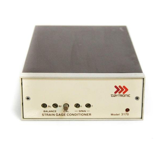
Summary of Contents for DayTronic 3170
- Page 1 SB.5.1 MODEL 3170 STRAIN GAGE CONDITIONER INSTRUCTION MANUAL 3000 Instrument Series...
- Page 2 No part of this document may be reprinted, reproduced, or used in any form or by any electronic, mechanical, or other means, including photocopying and recording, or in any information storage and retrieval system, without permission in writing from Daytronic Corporation. All specifications are subject to change without notice.
- Page 3 The I/O Wiring Data in Fig. 4 of this manual does not give the correct shield pairing of cable wires, which is shown in the revised diagrams below and on the following page: Daytronic 400 Series Daytronic 500 Series Transducer Connections...
- Page 4 Correction to Model 3170 Instruction Manual, v. SB.5.1 (cont’d) Daytronic 3X70 Instrument to Generalized Strain Gage Transducer +SENSE +EXC 4-Wire Configuration for Cables Shorter Than 20 Feet –SENSE +SIG –SIG SENSE 6-Wire Configuration for Cables –EXC Shorter Than 20 Feet...
- Page 5 Model 3170 Instruction Manual, v. SB.5.1 Pub. No. 3170M.5.1, Issued 03/01 Part No. 91132 MODEL 3170 STRAIN GAGE CONDITIONER INSTRUCTION MANUAL Daytronic Corporation Dayton, OH • Tel (800) 668-4745 www.daytronic.com...
-
Page 6: Table Of Contents
Specifications ..........PLEASE NOTE: Sections 6 and 7, Figures 8 and 9, and Table 2 have been removed from this manual. If you need information regarding specific 3170 components and circuitry, please contact the Daytronic Service Department at (937) 293-2566. -
Page 7: Description
Five-Volt Data Signal Level which is the output analog signal level of 3000 Series Modules. The 3170 has three separate analog outputs, each having a different bandpass: (1) dc to 2 kHz, (2) dc to 200 Hz, and (3) dc to 2 Hz. -
Page 8: Specifications
Model 3170 Table 1. Specifications 4-arm bridges, 90 to 2000 ohms, nominally 1 to 8 mv/v, full Transducers: scale (120 ohms or less requires use of 5-volt excitation). 4-, 5-, or 7-wire, depending on application; 1000 feet Cables: maximum length. Regulated 5 volts or 10 volts dc, selected with I/O Bridge Excitation: connector wiring. -
Page 9: Installation And Cabling
Figure 2. Panel cut-out dimensions for panel mounting are also shown in Figure 2. Up to four 3000 Series instruments can be mounted in a 19-inch rack using the 1.75-inch high Model 3004 Rack Adaptor. -
Page 10: Instrument Mounting Dimensions
Model 3170 A. Bench Mounting B. Rack Mounting C. Panel Mounting Figure 2. Instrument Mounting Dimensions... -
Page 11: Instrument Panel Mounting
Daytronic Corporation Figure 3. Instrument Panel Mounting... - Page 12 AC Power Connection. To protect operating personnel, the 3000 Series Mod- ules are equipped with a three-conductor power cord. When the cord is plugged into the appropriate receptacle, the instrument is grounded. The offset pin on the power cord is ground.
- Page 13 Transducer Cabling supplied module I/O connector. The I/O connector pin numbers and functions are given in Figure 4. When Daytronic 400 or 500 Series Transducers are used, factory-wired cables are available as shown in Figure 4. When user-fabricated transducer cabling is used, it should take the form of either the 4-, 5-, or 7-wire cable configuration shown in Figure 4.
-
Page 14: Calibration
Model 3170 Either 5-volt or 10-volt bridge excitation can be Transducer Excitation. selected. In general, 5-volt excitation is used with 120-ohm transducers, and the 10-volt excitation is used with 350-ohm devices. However, for any transducer which has a 4 mv/v or higher sensitivity, 5-volt excitation must be used to maintain proper operation without saturating the conditioner amplifiers. -
Page 15: O Wiring Data
See the CORRECTION to Fig. 4 in the front of this manual. Figure 4 I/O Wiring Data... - Page 16 See the CORRECTION to Fig. 4 in the front of this manual. Figure 4 (cont'd)
-
Page 17: Front-Panel Description
Daytronic Corporation BALANCE Controls: The coarse (R ) and fine (R ) BALANCE controls are used to set the module output to zero when the transducer is unloaded. SPAN Controls: The coarse (c) and fine (f) SPAN controls are used to set the output to the Equivalent Input value when the CAL button is pressed. -
Page 18: Block Diagram Description
Model 3170 calibration. To calibrate the instrument in the future, simply press the CAL button and adjust the SPAN controls to obtain the reading previ- ously recorded after dead weight calibration. If dead weight calibration is not practical and the transducer manufac- turer has supplied a calibration resistor (or resistor value), install the recommended calibration resistor. - Page 19 Daytronic Corporation mounted on the conditioner printed-circuit board. When the slide switch is ON, primary power is applied to the power transformer which provides the necessary power-line isolation and the low ac voltages required to develop the regulated dc voltages used in the module. The secondary of the power transformer has a grounded center tap, and a diode bridge functions as two full-wave rectifiers to produce ±...
-
Page 20: Verification Of Normal Operation
The user may also contact the factory Service Department or the local Daytronic Representative for assis- tance. If the module is suspected of faulty operation, observe the following steps. -
Page 21: Block Diagram
Figure 6. Block Diagram... - Page 22 This page intentionally blank.
-
Page 23: Star-Bridge Construction
Daytronic Corporation ity can be confirmed (or eliminated) by substituting a transducer and cable known to be in good condition or by simulating a balanced trans- ducer, using either a commercially available transducer simulator or the simple star bridge arrangement shown in Figure 7. The star bridge simulates a conventional four-arm bridge in an exact condition of ba- lance. - Page 24 Daytronic Corporation Dayton, OH • (800) 668-4745 www.daytronic.com...


Need help?
Do you have a question about the 3170 and is the answer not in the manual?
Questions and answers