Table of Contents
Advertisement
Quick Links
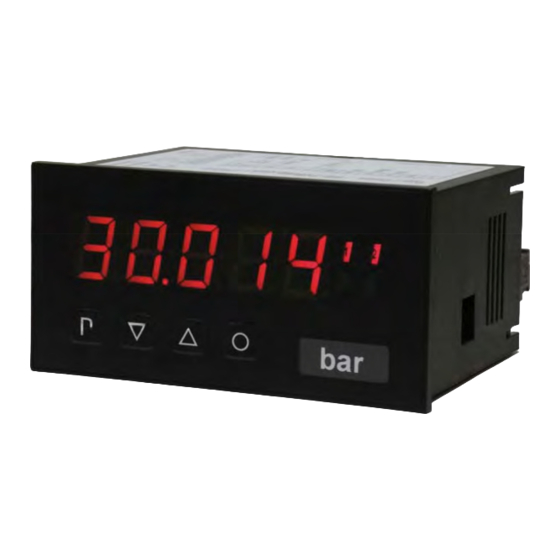
User manual M2
DMS amplifier with a calibration for 350 Ohm melt pressure sensors
Technical features:
• red display of -19999...99999 Digits (optional: green, orange, blue)
• minimal installation depth: 70 mm without plug-in terminal
• Min-/Max-memory
• 30 adjustable setpoints
• display flashing at threshold exceedance / threshold undercut
• zero key for triggering of HOLD, TARA or sensor calibration
• standard digital input for HOLD, TARA or sensor calibration
• sensor calibration with integrated switching output
• permanent MIN/MAX value metering
• arithmetic function
• zero point slowdown
• programming interlock via access code
• protection class IP65 (front side)
• pluggable screw-type terminal
• optional 2 relay outputs (changer)
M2_1MGB.pdf updated: 19.01.2012
96x48
Advertisement
Table of Contents

Related Manuals for DayTronic M2


Summary of Contents for DayTronic M2
- Page 1 User manual M2 DMS amplifier with a calibration for 350 Ohm melt pressure sensors Technical features: • red display of -19999…99999 Digits (optional: green, orange, blue) • minimal installation depth: 70 mm without plug-in terminal • Min-/Max-memory • 30 adjustable setpoints •...
- Page 2 Identification STANDARD TYPES ORDER NUMBER M2-1MR5B.020X.570BD Housing size: 96x48 mm M2-1MR5B.020X.670BD Options – breakdown product key: M 2- 1 M R 5 B. 0 2 0 X. 6 7 2 B D Standard type M-line Dimension D physical unit Installation depth 89 mm, incl.plug-in terminal...
-
Page 3: Table Of Contents
Contents Assembly Electrical connection Function and operation description Setting up the device 4.1. Switching on 4.2. Standard parameterisation (flat operation level) 4.3. Extended parameterisation (professional operation level) 4.3.1. Signal input parameters „INP“ 4.3.2. General device parameters „FCT“ 4.3.3. Safety parameters „COD“ 4.3.4. -
Page 4: Assembly
1. Assembly 1. Assembly Please read the Safety advices on page 37 before installation and keep this user manual for future reference. Gap for physical unit After removing the fixing elements, insert the device. Check the seal to make sure it fits securely. Click the fixing elements back into place and tighten the clamping screws by hand. -
Page 5: Electrical Connection
2. Electrical connection 2. Electrical connection... -
Page 6: Function And Operation Description
3. Function and operation description 3. Function and operation description Operation The operation is divided into three different levels. Menu level (delivery status) This level is for the standard settings of the device. Only menu items which are sufficent to set the device into operation are displayed. - Page 7 3. Function and operation description Function chart:...
-
Page 8: Setting Up The Device
4. Setting up the device 4. Setting up the device 4.1. Switching-on Once the installation is complete, you can start the device by applying the voltage supply. Before, check once again that all electrical connections are correct. Starting sequence For 1 second during the switching-on process, the segment test (8 8 8 8 8) is displayed followed by an indication of the software type and, after that, also for 1 second the software version. - Page 9 4. Setting up the device Menu level Parameterisation level Setting the decimal point, dot: The decimal point on the display can be moved with [▲] [▼] and confirmed with [P]. The display then switches back to the menu level again. Setting up the display time, SEC: then The display time is set with [▲] [▼].
- Page 10 4. Setting up the device Menu level Parameterisation level Special function digital input, dIG.In: … The above given parameters can be set for the operation mode onto the optional digital input aswell. See function description tASt.4. Threshold values / Limit values, LI-1: The limit value defines the threshold, that activates/deactivates an alarm.
- Page 11 4. Setting up the device Menu level Parameterisation level User code (4-digit number-combination, free available), U.CodE: If this code was set (>0000), all parameters are locked for the user, if LOC has been selected before under menu item run. By pressing [P] for 3 seconds in operation mode, the display shows COde.
-
Page 12: Extended Parameterisation (Professional Operation Level)
4. Setting up the device 4.3. Extended parameterisation (Professional operation level) 4.3.1. Signal input parameters Menu group level Menu level Menu level Parameterisation level Selection of the input signal tYPE: Available as measuring inputs are SENS.1 for 1 mV/V, SENS.2 for 2 mV/V and SENS.3 for 3.3 mV/V for known sensor sensibilities. - Page 13 4. Setting up the device Menu level Parameterisation level Setting of the comma / decimal point, dot: The decimal point of the display can be adjusted with [▲] [▼]. With [P] the selection is confirmed and the device changes back into menu level. Setting of the measuring time, SEC: dann The measuring time is adjusted with [▲] [▼].
- Page 14 4. Setting up the device Menu level Parameterisation level Setting up the physical unit, UnIt: One can choose between the above shown physical units. It will be displayed on the 5th digit of the display. Number of additional setpoints, SPCt: 30 additional setpoints can be defined to the initial- and final value, so linear sensor values are not linearised.
-
Page 15: General Device Parameters „Fct
4. Setting up the device 4.3.2. General device parameters Menu group level Menu level Menu level Parameterisation level Display time, DISEC: then The display is set up with [▲] [▼]. Thereby it jumps until 1 second in increments of 0.1 seconds and until 10.0 seconds in increments of 1.0. - Page 16 4. Setting up the device Menu level Parameterisation level Display, dISPL: With this function the absolute value, current measurand, Min-/Max value, totaliser value or the process-controlled Hold-value can be allocated to the display. With [P] the selection is confirmed and the device changes into menu level. Display flashing, FLASH: A display flashing can be added as additional alarm function either to single or to a combination of off-limit condition.
- Page 17 4. Setting up the device Menu level Parameterisation level Special function [O]-key, tASt.4: … For the operation mode, special functions can laid be on the [O]-key. This function is triggered by pushing the key. With tArA the display is tared to zero and is safed permanently as Offset.
-
Page 18: Safety Parameters „Cod
4. Setting up the device 4.3.3. Safety parameters Menu group level Menu level Menu level Parameterisation level User code U.Code : Via this code reduced sets of parameters can be set free. A change of the U.CodE can be done via the correct input of the A.CodE (master code). Master code, A.Code: By entering A.CodE the device will be unlocked and all parameters are released. - Page 19 4. Setting up the device Menu level Parameterisation level Release/lock alarm parameters, AL.LEU: This parameter describes the user relase/user lock of the alarm. - LIMIt, here only the range of value of the threshold values 1-4 can be changed. - ALrM.L, here the range of value and the alarm trigger can be changed. - ALL, all alarm parameters are released.
-
Page 20: Relay Functions „Rel
4. Setting up the device 4.3.4. Relay functions Menu group level Menu level Menu level Parameterisation level Alarm relay 1, rEL-1: The same applies for relays 2-4 …. …. Each setpoint (optional) can be linked up via 4 alarms (by default). This can either be inserted at activated alarms Al-1/4 or de-activated alarms Aln1/4. - Page 21 4. Setting up the device Menu level Parameterisation level Alarms for relay 1, CoM-1: …. The allocation of the alarms to relay 1 happens via this parameter, one alarm or a group of alarms can be chosen. With [P] the selection is confirmed and the device changes into menu level.
-
Page 22: Alarm Parameters „Al1
4. Setting up the device 4.3.5. Alarm parameters Menu group level Menu level Menu level Parameterisation level Dependency alarm 1, ALrM.1: The dependency of alarm 1 can be related to special functions, in detail these are the current measuring value, the MIN-value, the MAX-value or the totaliser-/sum-value. Is Hold selected, then the alarm is hold and processed just after deactivation of HOLD. -
Page 23: Programming Interlock, Run
4. Setting up the device Menu level Parameterisation level Function for threshold value undercut /exceedance, Fu-1: A limit value undercut is selected with Louu (for LOW = lower limit value), a limit value exceedance with High (for HIGH = higher limit value). If e.g. limit value 1 is on a threshold level of 100 and allocated with function High, an alarm is activated by reaching of the threshold level. -
Page 24: Sensor Calibration Offset/Final Value
4. Setting up the device 4.4. Sensor calibration offset / final value The device has an automatic calibration at mass pressure sensors, where an integrated switching output operates an often available 80% calibration. Like this offset and final value are adjusted, and the sensor can be applied directly after this. The calibration can be done via the 4th key or the digital input, depending on the parameterisation. -
Page 25: Alarms / Relay
4. Setting up the device 4.5. Alarms / Relays This device has 4 virtual alarms that can monitor one limit value in regard of an undercut or exceedance. Each alarm can be allocated to an optional relay output S1-S2; furthermore alarms can be controlled by events like e.g. -
Page 26: Factory Settings
5. Factory settings 5. Factory settings 5.1. Default values Standard parameterisation (flat oepration level) Parameter Menu items Default value Sensor Sensor Type of input 1 mV/V 2 mV/V 3,3 mV/V calibration calibration Final value Offset Display of decimal point Measuring 0.1 second 10.0 seconds 1.0 second... - Page 27 5. Factory settings Parameter Menu items Default value Limit value 1 Hysteresis 1 Exceedance Undercut Exceedance Operation type 1 Limit value 2 Hysteresis 2 Exceedance Undercut Exceedance Operation type 2 Usercode Master code Standard Parameter Professional Standard operation lock operation operation...
- Page 28 5. Factory settings Extended parameterisation (professional operation level) Signal input parameters Parameter Menu items Default value Type of input 1 mV/V 2 mV/V 3.3 mV/V Sensor Sensor calibration calibration Final value Offset Display of decimal point Measuring 0.1 second 10.0 1.0 second time seconds...
- Page 29 5. Factory settings Parameter Menu items Default value Number of setpoints Display value Analog value … Display value Analog value Display underflow Display overflow...
- Page 30 5. Factory settings General device parameters Parameter Menu items Default value Display time 0.1 second 10 seconds 1 second Value No rounding Increments of Increments of Increments of No rounding rounding Arithmetics none reciprocal square root root none value Zero point No slowdown at x-Digit no slowdown...
- Page 31 5. Factory settings Parameter Menu items Default value Digital none Tara function Set Tara value Extremun Display Sensor eingang reset measurand calibration temporary Sensor Hold Sliding Absolute value Tara calibration average value Alarm 4 Alarm 2 Alarm 1 Alarm 3 Safety parameters Parameter Menu items...
- Page 32 5. Factory settings Relay functions Parameter Menu items Default value Relay at Alarm 1 at Alarm 4 at Alarm 1 function1 not Alarm 1 not Alarm 4 via Logic fallen off tightened Logic relay 1 active if at active if no active if all active if at active if at...
- Page 33 5. Factory settings Parameter Menu items Default value Alarm combi- alarm 1 alarm 2 alarm 1 + 2 alarm 3 alarm 1 + 3 alarm 1 nation relay and so alarm on…up to 1+2+3+4 Alarm parameters Parameter Menu items Default value Alarm source current minimum...
- Page 34 5. Factory settings Parameter Menu items Default value Alarm source current minimum maximum totaliser hold current measurand measurand measurand measurand external input (DigIn/Tast4) Limit value 2 Hysteresis 2 Function 2 undercut exceedance exceedance Activation delay 2 100 seconds De-activation delay 100 seconds Parameter Menu items...
- Page 35 5. Factory settings Parameter Menu items Default value Function 3 undercut exceedance exceedance Activation delay 3 100 seconds De-activation delay 100 seconds Parameter Menu items Default value Alarm source current minimum maximum totaliser hold current measurand measurand measurand measurand external input (DigIn/Tast4) Limit value 4 Hysteresis 4...
-
Page 36: Reset To Factory Settings
5. Factory settings 5.2. Reset to default values To return the unit to a defined basic state, a reset can be carried out to the default values. The following procedure should be used: • Switch off the power supply • Press button [P] „- - - - -“... -
Page 37: Technical Data
6. Technical data 6. Technical data Housing Dimensions 96x48x70 mm (BxHxD) 96x48x89 mm (BxHxD) incl. plug-in terminal +0.8 +0.6 Panel cut-out 92.0 x 45.0 Wall thickness up to 15 mm Fixing Screw elements Material PC Polycarbonate, black, UL94V-0 Sealing material EPDM, 65 Shore, black Protection class Standard IP65 (Front side), IP00 (Back side) - Page 38 6. Technical data Output Sensor output 24 VDC / 50 mA; 10 VDC / 20 mA Analog output 0/4-20 mA or 0-10 VDC 16 Bit switchable Switching outputs Relay with change-over contacts 250 VAC / 5 AAC; 30 VDC / 5 ADC Switching cycles 30 x 10 at 5 AAC, 5 ADC ohm resistive burden...
-
Page 39: Safety Advices
Please inform the supplier immediately of any damage. Installation The M2-device must be installed by a suitably qualified specialist (e.g. with a qualification in industrial electronics). Notes on installation • There must be no magnetic or electric fields in the vicinity of the device, e.g. due to transformers, mobile phones or electrostatic discharge. -
Page 40: Error Elimination
8. Error elimination 8. Error elimination Error description Measures The unit permanently indicates • The input has a very high measurement, check overflow. the measuring circuit. • With a selected input with a low voltage signal, it is only connected on one side or the input is open. •...
Need help?
Do you have a question about the M2 and is the answer not in the manual?
Questions and answers