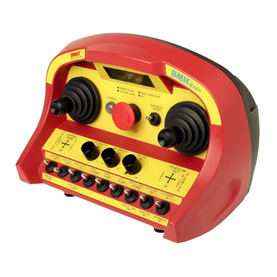
Table of Contents
Advertisement
Micro-control as
Front page "Operation and Maintenance Manual MC-3-series"
Operation and Maintenance Manual MC-3-series
This page is not a part of the customer manual
Revision
Date
2005.07.14
Written by
Checked by
Approved by
File name
G:\05\MAN\05-006-01 Operation and Maintenance Manual for MC-3-series
Revision history
Rev.
Changes
1
First revision
2
3
4
MAN-05-006
Document number
MAN-05-006
and shall not be distributed!
1
2
AB
JL
3
4
Page 1 of 1
5
Rev. 1
Advertisement
Table of Contents

Summarization of Contents
General Information
Main Parts of the System
Details the core components of the MC-3-series system, including terminal, belt, batteries, charger, base unit, and antenna.
Security and Safety Features
Covers system security functions like serial numbers, data checksum, joystick monitoring, activity checks, and relevant directives.
Environmental Operating Conditions
Specifies operating temperature ranges and IP ratings for the terminal, base unit, and battery charger.
System Documentation
Lists the accompanying documentation for the MC-3-series system, including manuals, diagrams, and specifications.
Operating and Maintenance
Terminal Operation
Provides general information on terminal operation, customer specifications, and necessary training for operators.
Terminal Maintenance
Details cleaning procedures, handling of rubber boots, and preventing dirt accumulation on the terminal.
Terminal Display Codes
Explains the meaning of LED indicators on the terminal for system status and error detection.
Terminal Physical Data
Lists the physical dimensions and weight for different models within the MC-3-series.
Battery Charger and Batteries
Covers battery operating time, lifespan, charging cycles, and general information.
Battery Replacement
Step-by-step instructions for safely replacing the battery in the terminal.
Battery Charger Installation and Use
Guidance on installing the battery charger and the procedure for charging batteries.
Battery Disposal
Instructions for the proper and legal disposal of batteries as hazardous waste.
Base Unit Installation
Requirements for installing the base unit, including electrical connection, environment, and vibration considerations.
Base Unit Maintenance
Notes on periodic inspection of the base unit for physical damage and corrosion.
Base Unit Display Codes
Information on how to interpret LED indications and displays for base unit fault finding.
Base Unit Physical Data
Mentions that base unit physical size and weight vary, with supplementary specifications available.
Carrying Belt Usage
Emphasizes the importance of using the carrying belt or strap for terminal safety and operator comfort.
Antenna Installation
Provides guidance on optimal placement and mounting of antennas for best performance.
Terminal Display Codes Explained
Steady Light Indicator
Indicates normal operation with OK battery and no detected fault.
Slow Flashing Light (1/sec)
Signifies low battery voltage; requires battery replacement.
Short Flashes (2/sec)
Indicates programming mode; requires terminal restart.
1 Flash with Long Stop
Signals a processor fault or test mode; requires checks and potential replacement.
2 Flashes with Stop
Indicates activity at start-up; requires joystick/switch reset.
3 Flashes with Stop
Denotes a radio fault; requires radio module replacement.
4 Flashes with Stop
Indicates shutdown due to low battery voltage; requires battery replacement.
5 Flashes with Stop
Signals a keyboard fault; indicates an input module issue.
6 Flashes with Stop
Indicates shutdown due to inactivity; requires terminal restart.
7 Flashes with Stop
Signals a priority stop activation; requires safety checks and restart.
BAT LED Not Lit
Indicates no LED signal; requires battery check and terminal restart.
Base Unit Display Codes
System ID Code Display
Shows the system ID, displayed briefly upon terminal power-on.
System ID and Terminal Number Display
Shows system ID and terminal number, for systems with multiple terminals.
Battery Voltage Display
Displays measured battery voltage in volts, typically between 6.40 and 9.00.
Programmable Analog Channel Display
Indicates the currently selected programmable analog channel during programming mode.
No Analog Channel Activated Display
Shown when no analog channel is selected in programming mode.
Base Unit Error E001
Processor fault or module fault indication; requires BOOT-jumper check and processor replacement.
Base Unit Error E002
Indicates activity at start-up; requires joystick/switch reset.
Base Unit Error E003
Signals a radio fault; requires radio module replacement.
Base Unit Error E004
Indicates shutdown due to low battery voltage; requires battery replacement.
Base Unit Error E005
Signals a keyboard fault; indicates an issue with the MC-ITX input module.
Base Unit Error E006
Indicates shutdown due to inactivity; requires terminal restart.
Base Unit Error E007
Signals a priority stop activation; requires safety checks and restart.

Need help?
Do you have a question about the MC-3000 and is the answer not in the manual?
Questions and answers