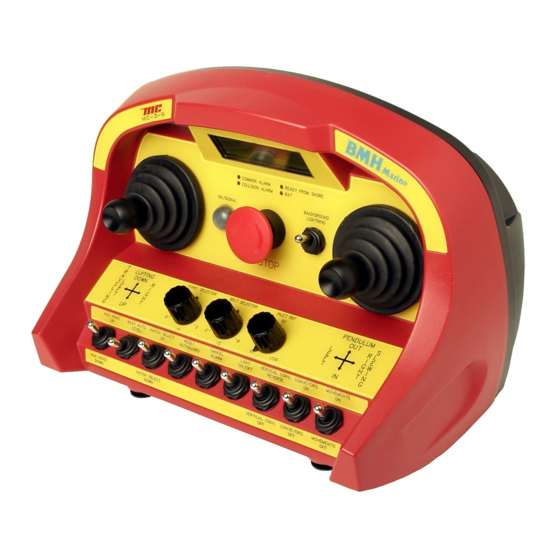
Cavotec MC-3-series Operation And Maintenance Manual

Cavotec MC-3-series Operation And Maintenance Manual

Industrial remote control

Advertisement

Micro-control as
Front page "Operation and Maintenance Manual MC-3-series"
Operation and Maintenance Manual MC-3-series
This page is not a part of the customer manual
Revision
Date
2005.07.14
Written by
Checked by
Approved by
File name
G:\05\MAN\05-006-01 Operation and Maintenance Manual for MC-3-series
Revision history
Rev.
Changes
1
First revision
2
3
4
MAN-05-006
Document number
MAN-05-006
and shall not be distributed!
1
2
AB
JL
3
4
Page 1 of 1
5
Rev. 1

Advertisement

Table of Contents
loading

Summary of Contents for Cavotec MC-3-series

  • Page 1 Micro-control as Front page ”Operation and Maintenance Manual MC-3-series” Page 1 of 1 Operation and Maintenance Manual MC-3-series Document number MAN-05-006 This page is not a part of the customer manual and shall not be distributed! Revision Date 2005.07.14 Written by...
  • Page 2 Micro-control as Operation and Maintenance Manual for MC-3-series Page 2 of 9 Operation and Maintenance Manual MC-3-series Document number MAN-05-006 MAN-05-006 Rev. 1...
  • Page 3: Table Of Contents

    Micro-control as Operation and Maintenance Manual for MC-3-series Page 3 of 9 Table of Contents General information........................4 The main parts of the system ....................4 Security/ Safety......................... 4 Environment..........................4 Documentation ......................... 5 Operating and Maintenance......................5 Terminal............................ 5 2.1.1...
  • Page 4: General Information

    • Antenna - located on or connected to the base unit with a coaxial cable. 1.2 Security/ Safety The MC-3-series system is produced to ensure safe control of machines. The following security functions are built into each:- • A unique serial number for each system, means one system cannot operate another.
  • Page 5: Environment

    This document deals with MC-3-series generally, and special instructions in the use of the terminal cannot be given here. The functions that are described in this chapter are common for all MC-3-series deliveries. Micro-control can supply manuals for specific machines if requested to do so.
  • Page 6: Physical Data

    Micro-control as. 2.3 Base unit All the MC-3-series base units are produced according to the customer’s specifications, the wiring diagram shows how the base unit is connected.
  • Page 7: Maintenance

    Micro-control as Operation and Maintenance Manual for MC-3-series Page 7 of 9 2.3.2 Maintenance • The base unit does not need any maintenance, but should be inspected periodically for physical damage and corrosion. 2.3.3 Display Codes If the base unit does not operate correctly, check the led indication and display for messages. Use the enclosed table for fault finding.
  • Page 8 Micro-control as Operation and Maintenance Manual for MC-3-series Page 8 of 9 6. Display Codes Table 1: Status Indications on the Terminal Flashing pattern Description Action Normal condition. The terminal is Steady light. turned on, the battery voltage is OK, None and no fault is detected.
  • Page 9 Micro-control as Operation and Maintenance Manual for MC-3-series Page 9 of 9 Table 2: Possible indications in the Base Unit display If the system has a 4 digit LED module the indicated codes are displayed there. If the system has a LCD module the error codes are displayed in a field in the display.

This manual is also suitable for:

Mc-3-5Mc-3-6Mc-3000

Table of Contents