Advertisement
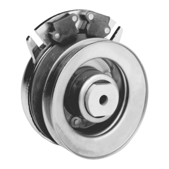
Commercial MagStop
P-1177-WE
819-0457
Residential, TG-2000 and
Installation & Operation Instructions
This Manual covers Magstop Product Families as outlined below:
Series
Reference Name
5217 Series
RMS
5218 Series
CMS
5219 Series
TG 2000
5228 Series
CMS 250
Clutch/Brake
®
Torque Range
60 & 80 ft-lb.
175 & 200 ft-lb.
105 & 125 ft-lb.
225 & 250 ft-lb.
Advertisement
Troubleshooting

Summarization of Contents
MagStop Bearing Mounted Clutch and Clutch/Brake Assemblies
Rotor Assembly Description
Input of the clutch; includes keyed hub mating with crankshaft keyway.
Armature Assembly Description
Output of the clutch; consists of disk, springs, and pulley or output flange.
Field Assembly Description
Clutch power source containing the coil generating magnetic attractive force.
Brake Poles Function
Permanent magnets providing brake torque when clutch is disengaged.
D-drive Spacer Function
Hub inserted into armature or field bearing to prevent crankshaft rotation.
Anti-rotation Slot Function
OEM device preventing MagStop rotation with crankshaft.
Optional Washer Requirement
Minimum .250 inch thick steel washer required if D-drive spacer is not used.
MagStop Components Diagram
D-drive Spacer Removal/Installation
Procedure for removing and installing the D-drive spacer using an arbor press.
Requirements for Successful Clutch Application/Installation
Critical Application Requirements
Key requirements for successful clutch application: anti-rotation free-play and mounting bolt torque.
Mounting Instructions
Typical Engine Installation with Ground Drive Pulley
Illustration of typical engine installation with ground drive pulley, showing shaft and spacer clearance.
Anti-Rotation Mounting Considerations
Diagram illustrating anti-rotation slots and their function in mounting.
Anti-Rotation Installation Examples
Bracket Orientation and Fit Guidance
Guidance on correct bracket orientation, fit, and avoiding binding in anti-rotation slots.
Incorrect Bracket Orientation Example
Example of incorrect anti-rotation bracket orientation leading to binding.
Anti-Rotation Installation Details
Clearance and Non-Contact Requirements
Ensuring proper clearance between bracket and field shell, and non-contact areas.
Correct Bracket Fit Specification
Specifying minimum loose fit and stackup for correct anti-rotation bracket operation.
Anti-Rotation Installation Details 2
Twisted Area Clearance and Fit
Ensuring twisted areas of bracket do not contact field shell and maintaining fit.
Anti-Rotation Installation Details 3
Screw Movement and Loose Fit
Details on screw movement allowance and minimum loose fit for anti-rotation brackets.
Anti-Rotation Installation Details 4
Aircraft Cable Slack Specification
Using aircraft cable with minimum slack for anti-rotation.
Anti-Rotation Installation Details 5
Combined Loose Fit Specification
Ensuring combined loose fit for anti-rotation bracket components.
Anti-Rotation Installation Details 6
Final Fit and Stackup Check
Checking final fit and stackup to avoid bottoming in anti-rotation slot.
Troubleshooting Checklist
Clutch Will Not Engage Issues
Common causes and solutions for clutch engagement problems like blown fuse or low voltage.
Brake Will Not Engage Issues
Causes and solutions for brake engagement failure, including worn parts or contamination.
Clutch Slip Issues
Troubleshooting causes for clutch slip, such as low voltage, inadequate supply, or overload.
Troubleshooting Checklist Continued
Noisy Clutch/Vibration Issues
Causes and solutions for noise or vibration, including bearing failure and loose mounting.
Clutch Mounting and Squareness Issues
Addressing issues related to clutch mounting, alignment, and fit.
Burnishing Procedure for New Clutch/Brake
Procedure to break in a new clutch/brake, involving engagement and disengagement cycles.
Electrical Evaluation
How to Measure Clutch Coil Resistance
Step-by-step guide to measure clutch coil resistance using a meter.
Measure Supply Voltage at Clutch
Procedure to measure supply voltage at the clutch connector for proper operation.
Model Resistance and Torque Specifications
Table listing clutch models, torque ratings, and acceptable resistance ranges.
Re-gap Adjustment Procedure
When to Remove Shim
Guidance on when to adjust the air gap by removing shims due to wear.
Component Identification Reference
Diagram identifying key components for re-gap adjustment.
Procedure for Air Gap Adjustment
Steps for checking and adjusting the air gap using feeler gauges and shims.
Re-gap Adjustment Procedure Continued
Loosening and Removing Brake Mounting Bolts
Steps for loosening mounting bolts and removing the re-gap shim.
Confirming Minimum Air Gap
Checking for the required minimum air gap between rotor and armature face.
Retorquing Bolts and Clutch Cycling
Retorquing bolts to specification and cycling the clutch to ensure proper function.
Re-gap Adjustment Procedure Continued 2
Perform Safety Check
Ensuring deck is not engaged when PTO switch is off or clutch is de-energized.
Mounting Bolt Torque Specifications
Table of torque values for different thread sizes of mounting bolts.
Warranty Information
Warner Electric LLC Product Warranty
Details on warranty coverage, duration, and limitations for products.
Changes in Dimensions and Specifications
Note regarding potential changes in product dimensions and specifications without notice.


Need help?
Do you have a question about the 5217 Series and is the answer not in the manual?
Questions and answers