Advertisement
AUDIO-VIDEO SURROUND RECEIVER
KRF-V5100D/V5100D-S
KRF-V6100D/V6100D-S
SERVICE MANUAL
Knob *
(K29-)
STANDBY
ON/STANDBY
SPEAKERS ON/OFF
DIMMER
POWER
ON
OFF
PHONES
ACTIVE EQ
Phone jack
(E11-0271-05)
Knob(BUTTON) *
Foot
(K27-)
(J02-1464-03)
Pin ass'y
Pin ass'y
(E63-1374-05)
(E63-1375-05)
COMPONENT VIDEO
VIDEO 2 IN
AM
Y
CB
CR
Y
CB
DVD IN
VIDEO
DVD
IN
MONITOR
L
OUT
VIDEO 2
IN
R
REC OUT PLAY IN
AUX
CD/DVD
VIDEO 1
VIDEO 1
IN
OUT
Pin jack
Pin jack
(E63-1368-05)
(E63-1372-05)
Pin jack
(E63-1371-05)
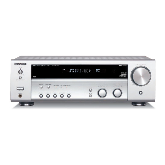
Illust. is KRF-V5100D.
* Refer to parts list on page 23.
Front glass *
(B10-)
LISTEN MODE
ACTIVE EQ
DTS DOLBY DIGITAL
INPUT MODE
BAND
AUTO/MONO
MEMORY
Knob *
(K29-)
Escutcheon *
(B07-)
Optical receiving module
Tuner ass'y
(W02-2802-05)
(W02-4609-05)
Pin jack
(E63-1369-05)
COAXIAL OPTICAL
VIDEO 2
ANTENNA
FM
GND
75
DVD/6CH
CR
DIGITAL IN
AUDIO
DVD/6CH INPUT
CENTER
REC OUT PLAY IN
PLAY IN
SUB
FRONT
SURROUND
WOOFER
MD / TAPE
VIDEO 1
VIDEO 2
Pin jack
(E63-1372-05)
Pin jack
Pin jack
(E63-1370-05)
(E63-1373-05)
Panel *
(A60-)
MULTI CONTROL
INPUT SELECTOR
SOUND
SETUP
Knob *
Knob *
(K29-)
(K29-)
AC outlet *
Pin jack
(E03-)
(E63-1407-05)
L
SURR BACK
CD / DVD
R
SURR BACK
PRE OUT
SURROUND
FRONT
CENTER
+
+
-
-
R
L
C
R
L
GRAY
BLUE
RED
WHITE
GREEN
SUB WOOFER
PRE OUT
SPEAKERS (8-16 )
Pin jack
Lock terminal board
(E63-1146-05)
(E70-1004-05)
Lock terminal board
(E70-1024-05)
© 2006-5 PRINTED IN KOREA
B51-5985-00 (K/K) 219
Knob *
Escutcheon *
(K29-)
(B07-)
VOLUME CONTROL
DOWN
UP
MUTE
Foot
(J02-1464-03)
Metallic cabinet *
(A01-)
AC OUTLETS
AC power cord *
(E30-)
Power cord bushing
(J42-0349-05)
Knob *
(K29-)
Advertisement
Table of Contents

Related Manuals for Kenwood KRF-V6100D


Summarization of Contents
Front and Rear Panel Identification
Front Panel Components
Identifies knobs, buttons, jacks, and displays on the front panel.
Rear Panel Connectivity
Details audio, video, speaker, and power connections on the rear panel.
Unit Accessories and Cautions
Included Accessories
Lists all accessories provided with the receiver unit.
Operational Cautions and Warnings
Provides safety, environmental, and operational guidance for the unit.
PC Board Component Layouts
Side A (X08-3472-70) Layout
Locates and identifies components on the primary circuit board.
Side B (X08-3472-70) Layout
Locates and identifies components on the secondary circuit board.
X09-7012-70 Board Layout
Identifies components on the X09-7012-70 circuit board.
X09-7012-70 Board Layout (Continued)
Continues component identification for the X09-7012-70 circuit board.
X14-8022-70 Board Layout (Part 1)
Identifies components on the X14-8022-70 circuit board (Part 1).
X14-8022-70 Board Layout (Part 2)
Continues component identification for the X14-8022-70 circuit board (Part 2).
X25-6772-70 Board Layout
Identifies components on the X25-6772-70 circuit board.
X14-8022-70 Board Layout (Part 3)
Continues component identification for the X14-8022-70 circuit board (Part 3).
X14-8022-70 Board Layout (Part 4)
Continues component identification for the X14-8022-70 circuit board (Part 4).
X14-8022-70 Board Layout (Part 5)
Continues component identification for the X14-8022-70 circuit board (Part 5).
X14-8022-70 Board Layout (Part 6)
Continues component identification for the X14-8022-70 circuit board (Part 6).
X09-7012-70 Board Layout (Part 1)
Identifies components on the X09-7012-70 circuit board (Part 1).
X09-7012-70 Board Layout (Part 2)
Continues component identification for the X09-7012-70 circuit board (Part 2).
X14-8022-70 Board Layout (Part 7)
Continues component identification for the X14-8022-70 circuit board (Part 7).
X14-8022-70 Board Layout (Part 8)
Continues component identification for the X14-8022-70 circuit board (Part 8).
X14-8022-70 Board Layout (Part 9)
Continues component identification for the X14-8022-70 circuit board (Part 9).
Schematic Diagrams
IC300 and IC800 Series Schematics
Partial schematics for integrated circuits in the unit's main processing sections.
IC400 Series and Other IC Schematics
Partial schematic views for various ICs used in the device.
Model and Destination Information
Model-Specific Unit Number Table
Correlates model variants with unit numbers and destinations.
Exploded View of the Unit
Unit Assembly Diagram
Visual representation of the unit's components and their assembly order.
Parts List
KRF-V5100D/V6100D Component Identification
Detailed listing of all parts with part numbers and descriptions.
KRF-V5100D/V6100D Component Identification (Continued)
Continues the detailed listing of all parts for the unit.
KRF-V5100D/V6100D Component Identification (Continued)
Continues the detailed listing of all parts for the unit.
KRF-V5100D/V6100D Component Identification (Continued)
Continues the detailed listing of all parts for the unit.
KRF-V5100D/V6100D Component Identification (Continued)
Continues the detailed listing of all parts for the unit.
KRF-V5100D/V6100D Component Identification (Continued)
Continues the detailed listing of all parts for the unit.
Product Specifications
Specifications for Europe
Technical specifications for the European market version of the unit.
Specifications for Australia
Technical specifications for the Australian market version of the unit.
Need help?
Do you have a question about the KRF-V6100D and is the answer not in the manual?
Questions and answers