Table of Contents
Advertisement
OPERATOR'S AND SERVICE MANUAL
MANUAL NUMBER 152-B
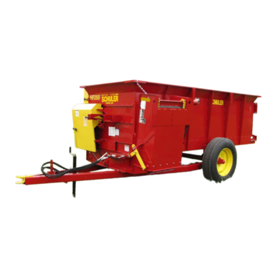
MODELS HF255, HF295
!!!WARRANTY REGISTRATION INSIDE MUST BE COMPLETED AND
RETURNED WITHIN 15 DAYS OF INVOICE SALE DATE OR WARRANTY
IS REDUCED!!! DON'T LOSE YOUR FULL WARRANTY!!!
SCHULER MFG. & EQUIP. CO., INC.
63724 RICHLAND ROAD
GRISWOLD, IOWA 51535
PHONE - 712-774-2228
FAX - 712-774-2230
E-mail:
schuler@schulermfg.net
Web Page:
www.schulermfg.net
1
Advertisement
Chapters
Table of Contents

Related Manuals for Schuler HF295


Summary of Contents for Schuler HF295
- Page 1 MODELS HF255, HF295 !!!WARRANTY REGISTRATION INSIDE MUST BE COMPLETED AND RETURNED WITHIN 15 DAYS OF INVOICE SALE DATE OR WARRANTY IS REDUCED!!! DON’T LOSE YOUR FULL WARRANTY!!! SCHULER MFG. & EQUIP. CO., INC. 63724 RICHLAND ROAD GRISWOLD, IOWA 51535 PHONE - 712-774-2228...
- Page 2 Schuler Mfg. & Equip. Co., Inc., to validate the machine warranty. MANUAL REVISIONS A. All HF255 ending in Serial Number 333 and up have new 25B01 PTO Assembly, 4-30-2003. B. Added Hydraulic Drive. C. Added HF295, 6-10-2010. D. Added HF295 Hydraulic Floor, 11-14-2010.
-
Page 3: Warranty
PH: 712-774-2228 ~ FAX: 712-774-2230 This Manufacturer’s Limited Warranty (“Limited Warranty”) is effective with respect to Schuler Products sold by dealers after September 1, 2006, until revised by Schuler Mfg. & Equip. Co., Inc. (“Schuler”). General Provisions. The limited express warranties described in this Limited Warranty are provided by Schuler to the original purchasers of new equipment manufactured by Schuler that is purchased from authorized Schuler dealers. - Page 4 (vi) minor fluid seepage or moisture on the outside of parts. Schuler does not provide any warranty with respect to any vehicles on or in which parts or equipment manufactured by Schuler have been installed and Schuler...
- Page 5 Schuler of actual damages in an amount not to exceed the amount paid for the product. This Limited Warranty gives you specific legal rights, and you may also have other rights which vary from state to state.
- Page 6 1. Dealer must hold parts submitted for Warranty Claims for a period not to exceed sixty (60) days from the date Dealer receives claim. 2. Schuler will, within the sixty (60) day period referred to in Paragraph 1, inform Dealer if a part is to be sent to Schuler.
- Page 7 Schuler Manufacturing and Equipment Co., Inc. and purchased by buyer (The “truck”) and (II) that Schuler Manufacturing and Equipment Co., Inc. purchased the truck in used condition from a third party. The purchaser agrees that the truck is being sold by Schuler Manufacturing and Equipment Co., Inc.
-
Page 9: Table Of Contents
CONTENTS HF255, HF295 OPERATION Warranty............................Front A Word from the Company Founder..................1 Introduction..........................1 Specifications..........................2 Safety............................3-5 Operator Qualifications....................... 6 Operator Sign-Off Form....................... 6 Before Using Your New Machine....................7 Preparing the Tractor........................8 Hitching to the Tractor........................ 9 Safety Chain.......................... -
Page 10: Introduction
A WORD FROM THE FOUNDER If this is your first Schuler Built Product, “WELCOME ABOARD”. You are now part of a very large growing family. Although we are talking about thousands of people, we still like to think of each one of our customers as a member of the Schuler Family. -
Page 11: Specifications
SERIAL NUMBER AND MODEL NUMBER The Serial Number and the Model Number of the Schuler HF Feeder is found on the rear, right hand frame of the wagon. The serial number is stamped on a plate riveted into the frame just above the spring tightener. -
Page 12: Safety
SAFETY UNDERSTAND SAFETY WORDS AND SYMBOLS This SAFETY ALERT SYMBOL is used in this manual whenever personal safety is involved and means ATTENTION! BECOME ALERT! It stresses an attitude of “HEADS UP” for safety. Read and understand all pages in this manual that bear this safety symbol and……TAKE TIME TO BE CAREFUL! The header of safety decals on this equipment contain a signal word and color code to indicate the severity level of the hazard. - Page 13 SAFETY OPERATING SAFETY PRECAUTIONS When the mixer / feeder is in operation it has many moving parts which could cause severe injury or death to persons coming in contact with these parts. To help avoid serious accidents, the following guidelines should always be followed. BE SURE ALL SAFETY SHIELDS are in place before operating, including driveline shields.
- Page 14 Safety tow chain may be ordered as an option from Schuler Mfg. Safety tow chain illustrated page 9. For towing a 10,000 lb. maximum gross weight, order Schuler P.N. 34T10-0000 safety tow chain.
-
Page 15: Operator Qualifications
INSTRUCTIONS IS A MISUSE OF THE EQUIPMENT! SIGN-OFF FORM Schuler follows the general standard specified by the American Society of Agricultural Engineers (ASAE) and the Occupational Safety and Health Administration (OSHA). Anyone who will be operating and/or maintaining this equipment must read and clearly understand ALL SAFETY, OPERATING AND MAINTENANCE information presented in this manual. -
Page 16: Before Using Your New Machine
BEFORE USING YOUR NEW MACHINE When towing a new machine, stop and feel the wheel hubs after 6-10 miles. If hub is hot to the hand, remove hub cap and back spindle nut off 1/4 – 1/2 turn. Check for proper assembly and adjustments. Make sure all lift flight bolts, floor flight bolts, hitch bolts, wheel bolts, sprocket and pulley set screws, etc. -
Page 17: Preparing The Tractor
PREPARING THE TRACTOR Mechanically driven Schuler feed wagons may only be used on tractors with 540 RPM PTO drives. No limitations are placed on tractor horsepower; however, a minimum of 40 horsepower is recommended for most applications. The tractor PTO shaft must be centered directly above the tractor drawbar. Do not operate with tractor drawbar set off to one side, damage to PTO U-joint could occur. -
Page 18: Hitching To The Tractor
HITCHING TO THE TRACTOR Attach mixer/feeder to the tractor drawbar using an adequate sized hitch pin with a locking retainer pin so hitch pin cannot bounce out. Raise jack and lock in horizontal position. Depress the spring loaded bushing on the PTO yoke and slide it on the tractor PTO shaft. Be sure the lock ring snaps back into the groove of the PTO shaft. - Page 19 LOADING In winter weather before loading, be sure the floor apron and elevator are not frozen to the floor. BEGIN LOADING THE MIXER/FEEDER AT THE FRONT END AND WORK TOWARD THE BACK. When unloading, to avoid damage to the PTO drive parts, the PTO shaft must be kept straight. For best mixing action, load each ingredient in a layer across the length of the box.
- Page 20 ADJUSTMENTS FLOOR APRON CONTROL CAUTION – DO NOT REMOVE SHIELDS, LUBRICATE OR ADJUST WHILE MACHINE IS RUNNING. SHUT OFF TRACTOR OR POWER SOURCE AND REMOVE IGNITION KEY. FLOOR APRON SPEEDS The floor apron speed control lever in the first notch, lever completely pushed in disengages the floor apron.
- Page 21 ADJUSTMENTS FLOOR APRON CONTROL WHEN CHECKING OR ADJUSTING FLOOR APRON SPEEDS, HAVE TRACTOR PTO DRIVELINE DISCONNECTED FROM THE TRACTOR, AND WAGON EMPTY. STEP 1 – Have PTO driveline laying straight forward over the hitch, disconnected from the tractor. STEP 2 – Open lower shield. Pull downward on drive belt as it comes off the jack shaft drive pulley.
-
Page 22: Floor Apron Adjustments
ADJUSTMENTS FLOOR APRON The floor apron on your Schuler Mixer has been designed for maximum strength and long life. Pintle chain is standard equipment with a much higher strength than 67X steel detachable chain. The apron driving sprockets should push against the barrel end of the pintle link, not the pin. - Page 23 FLOOR APRON CHAIN ADJUSTMENT Periodically inspect the spring tighteners on the floor apron at the rear of the box. When the spring tighteners have pushed the rear apron shaft to the rear of the tightener slot, the chain adjustment is completely used up.
-
Page 24: Discharge Conveyor Adjustment
DISCHARGE CONVEYOR CHAIN ADJUSTMENT Lower 4’ feeder extension down to the lowest position. Place a 1-1/2” tall block under a crossbar 2’ back from the outer end of the 4’ feeder extension. Tighten conveyor chain so that crossbar is snug on the block but can still be removed by hand from under the crossbar. Make sure conveyor chain is equal tightness on both sides by sliding block under the crossbar close to each side chain. -
Page 25: Axle Setting And Adjustment
AXLE SETTING AND ADJUSTMENT The axle is set at the factory for proper weight distribution between the hitch and axle, and no further adjustment should be necessary. Loading should always start at the front of the mixer/feeder and work towards the back. TIGHTEN 8-BOLT WHEELS TO 85-105 FOOT POUNDS TORQUE. -
Page 26: Lubrication
The Schuler Mixer/Feeder is designed to require a minimum amount of lubrication, with precision, triple lip, sealed bearings widely used. However, the points that are to be lubricated should be serviced regularly, at the intervals listed. - Page 27 Sprocket, cast – Page 32, Ref 2. WHEEL BEARINGS Repack wheel bearings once a year or every 1000 hours of operation HF255/HF295 wheel bearings – Page 10, Ref. 4 & 8. BEATER DRIVE AND IDLER Lubricate 1 pump of grease every 25 hours of use.
- Page 29 MODELS HF255, HF295 !!!WARRANTY REGISTRATION INSIDE MUST BE COMPLETED AND RETURNED WITHIN 15 DAYS OF INVOICE SALE DATE OR WARRANTY IS REDUCED!!! DON’T LOSE YOUR FULL WARRANTY!!! SCHULER MFG. & EQUIP. CO., INC. 63724 RICHLAND ROAD GRISWOLD, IOWA 51535 PHONE - 712-774-2228...
- Page 30 Schuler Mfg. & Equip. Co., Inc., to validate the machine warranty. MANUAL REVISIONS A. All HF255 ending in Serial Number 333 and up have new 25B01 PTO Assembly, 4-30-2003. B. Added Hydraulic Drive. C. Added HF295, 6-10-2010. D. Added HF295 Hydraulic Floor, 11-14-2010.
- Page 31 HF255 V-Belt Drive........................7 HF255 Floor Speed Control......................8 HF255 Ratchet and Apron Drive....................9 HF255, HF295 Axle........................10-11 HF255 PTO Input Shaft and Drive....................12-13 Beater Drive..........................14-15 HF255 Front Hydraulic Drive....................... 16 Hydraulic Drive Conveyor......................17 HF295 Beater and Apron Drive, Hyd. Floor................18-19 HF295 Floor Apron Drive......................
- Page 32 NOTES...
-
Page 33: When Ordering Parts
WHEN ORDERING PARTS To order parts for your Schuler equipment, please contact your local Schuler dealer. For information on dealers near you, contact Schuler Mfg. directly at 712-774-2228. Always have the following information available for phone orders or included in your written order:... -
Page 34: Safety And Operational Decals
DECAL, FLOOR SPEEDS, FOR RATCHET DRIVE UNITS 10010-0750 DECAL, MANUAL BRACKET SERIAL NO. IF MANUAL IS MISSING... 10010-0100 DECAL, SCHULER, QUALITY BUILT, TDC 10010-0101 DECAL, SCHULER, 4 * 20, TDC 10010-0161 DECAL, MODEL, 'HF255', TDC 10010-0163 DECAL, MODEL, 'HF295', TDC - 2 -... - Page 35 SAFETY DECALS NOTICE: Immediately replace all worn or damaged decals. Please supply the unit’s Serial Number with decal part number when ordering. - 3 -...
-
Page 36: Pto Assembly
PTO ASSEMBLY HF-000010 ITEM PART NUMBER DESCRIPTION 25B01-572010351 YOKE RS, SIZE 1, 1 3/8, TRACTOR TWIST LOCK 25B01-41201 PTO U-JOINT CROSS REPAIR KIT (B&P #41201) 25B01-204016851 SIZE # 1 OUTER TUBE YOKE 25B01-341036000R10 SIZE # 1 FLEX PIN OUTER 25B01-225021095 SIZE # 1 OUTER CARDIN TUBE 25B01-225011095 SIZE # 1 INNER CARDIN TUBE... - Page 37 SHIELDS HF255 HF-000020 ITEM PART NUMBER DESCRIPTION 0-260160 SHIELD, LOWER RCHT DRIVE, RH SIDE, SWING AWAY 0-260165 SHIELD, UPPER RCHT DRIVE, RH SIDE, SWING AWAY 0-260171 SHIELD, V-BELT DRIVE, FRONT SWING AWAY 39011-0000 SHIELD LATCH, LARGE RUBBER 39011-0001 SHIELD LATCH BRACKET, LARGE...
-
Page 38: Hitch And Jack Mounting
HITCH AND JACK MOUNTING HF-000030 ITEM PART NUMBER DESCRIPTION 0-260050 HITCH ASSY, LH SIDE, HF255 0-260241 HITCH ASSY, LH SIDE, HF295 0-260051 HITCH ASSY, RH SIDE, HF255 0-260242 HITCH ASSY, RH SIDE, HF295 0-162402 TRACTOR HITCH BRACKET, 3/4 THICK PLATE 0-162410 TRACTOR HITCH BRACKET, 1"... - Page 39 V-BELT DRIVE HF255 HF-000040 ITEM PART NUMBER DESCRIPTION 0-411012 PTO ALIGNMENT PULLEY & SPROCKET HF 1 B 1/4 KW 13070-1C06 FLAT IDLER, C-BELT, 7 OD, 5/8 BORE 13134-1C10 V-PULLEY, C-BELT, 13 1/2 OD, 1 1/4 B, 1/4 KW 13070-1C05 V-BELT IDLER, C-BELT, 7 OD, 5/8 BORE...
- Page 40 FLOOR SPEED CONTROL HF255 HF-000050 ITEM PART NUMBER DESCRIPTION 0-510806 FLOOR SPEED LEVER, USED W/SPRING 5/8 CRR * 23 0-158000 ARM FOR FLOOR APRON CONTROL FOR LH DISCHARGE 73E00-0410 1/4 * 1 1/4 SPRING PIN, ZP 0-157000 LEVER, LINKAGE TUBE, 7/8 OD * 5/8 ID * 30 OAL...
- Page 41 RATCHET AND APRON DRIVE HF255 HF-000090 ITEM PART NUMBER DESCRIPTION 72M12-0014 MACHINE BUSHING, 3/4 ID * 1 1/4 OD * 14 GA, ZP 73C00-0210 1/8 * 1 1/4 COTTER PIN STEEL, EXTENDED PRONG TAPER PT. ZP 16R10-RP06 RCHT PAWL, 3/4 B, 1 5/8 WIDE...
-
Page 42: Hf255, Hf295 Axle
HF255, HF295 AXLE HF-000060 - 10 -... - Page 43 HF255, HF295 AXLE ITEM PART NUMBER DESCRIPTION 0-260250 AXLE ASSEMBLY WELDMENT, HF255 0-260240 AXLE ASSEMBLY WELDMENT, HF295 2022A-0180 SPINDLE ASSY, HF255 2024P-0198 SPINDLE ASSY, HF295 180CR26260 GREASE SEAL, 2.63 ID * 3.63 OD 180CR27541 GREASE SEAL, 2.75 ID * 4.003 OD...
- Page 44 PTO INPUT SHAFT AND DRIVE HF255 HF-000070 - 12 -...
- Page 45 PTO INPUT SHAFT AND DRIVE HF255 ITEM PART NUMBER DESCRIPTION 71RC2-0100 5/8-11 NUT, ZP 72LH0-0100 5/8 SPLIT LOCK WASHER, ZP 72M10-0014 MACHINE BUSHING, 5/8 ID * 1 1/8 OD * 14 GA, ZP 13070-1C06 FLAT IDLER, C-BELT, 7 OD, 5/8 BORE...
-
Page 46: Beater Drive
HF255 BEATER DRIVE HF-000080 - 14 -... - Page 47 HF255 BEATER DRIVE ITEM PART NUMBER DESCRIPTION 13134-1C10 V-PULLEY, C-BELT, 13 1/2 OD, 1 1/4 B, 1/4 KW 0-216000 CLIP GUIDE FOR V-BELT, 10 GA * 1 1/2 * 2 3/4 11050-1510 SPKT 50B15HT, 1 1/4 B, 1/4 KW, 2SS...
- Page 48 FRONT HYDRAULIC DRIVE HF255 HF-000100 ITEM PART NUMBER DESCRIPTION 33BA0-0008 WOODRUFF KEY, AB, AC, AE MOTOR 0-260331 HYD DRIVE MOTOR MOUNT, 7 GA * 6 * 13 33BAG-0000 HYD MOTOR, 11.9 CU IN 11050-1308 SPKT 50B13HT, 1 B, 1/4 KW, 2SS...
-
Page 49: Hydraulic Drive Conveyor
HYDRAULIC DRIVE CONVEYOR HF-000110 ITEM PART NUMBER DESCRIPTION 73E00-0410 1/4 * 1 1/4 SPRING PIN, ZP 0-260147 HYD MOTOR MOUNT, BOLT-ON 72M10-0014 MACHINE BUSHING, 5/8 ID * 1 1/8 OD * 14 GA, ZP 26000-1000 SHAFT COUPLER, 1 5/8 OD * 1 ID * 3 OAL, 1/4 KW PN #511450 0-700453 CONVEYOR MOTOR MOUNT 3/8 * 8 * 8 33BAM-0000... - Page 50 BEATER AND APRON DRIVE HF295 HYDRAULIC FLOOR HF-000121 - 18 -...
- Page 51 BEATER AND APRON DRIVE HF295 HYDRAULIC FLOOR ITEM PART NUMBER DESCRIPTION 16B55-0512 BRG CAST SLEEVE, 1 17/32 B, 4 LONG 0-450015 SHAFT, BEATER IDLER 1 1/4 CRR * 9 1710B-1010 BEARING 1 1/4 B, W/BRONZE SLEEVE, RELUBE, 800 SERIES 0-260265 SHAFT, BEATER DRIVE, 1 1/4 CRR * 11 11060-7212 SPKT 60B72, 1 1/2 B, 3/8 KW, 2SS...
- Page 52 FLOOR APRON DRIVE HF295 HF-000130 ITEM PART NUMBER DESCRIPTION 0-260261 SHAFT, FLOOR APRON DRIVE 1 1/2 CRR * 70 1/4 , (3) 3/8 KW 11060-7212 SPKT 60B72, 1 1/2 B, 3/8 KW, 2SS 72M24-0014 MACHINE BUSHING, 1 1/2 ID * 2 1/4 OD * 14 GA, ZP 73E00-0416 1/4 * 2 SPRING PIN, ZP 0-130218...
-
Page 53: Hf295 Hydraulic Floor Drive Diagram
HF295 HYDRAULIC FLOOR DIAGRAM HF-000140 FOR SERIAL NUMBERS UP TO 158 ITEM PART NUMBER DESCRIPTION 33L00-2000 FLOW CONTROL W/RELIEF VALVE, 16 GPM 33HT6400-10-12 7/8-14 37^ JIC TO 1 1/16-18 O-RING 33HT6804-10 7/8-14 JIC & 7/8-14 O-RING TO 7/8-14 JIC RUN TEE 33PH3-0300 5/8-4000 PSI * 30, 10FJX90 &... - Page 54 HF295 HYDRAULIC FLOOR DIAGRAM HF-000230 FOR SERIAL NUMBERS 159 AND UP ITEM PART NUMBER DESCRIPTION 33L00-2000 FLOW CONTROL W/RELIEF VALVE, 16 GPM 33HT6400-10-12 7/8-14 37^ JIC TO 1 1/16-18 O-RING 33HT6804-10-12-10 HYD FITTING, RUN TEE MJIC XMORB 33PH3-0300 5/8-4000 PSI * 30, 10FJX90 & 10FJX 33HT6400-10 7/8-14 37^ JIC TO 7/8-14 O-RING 33BAM-0000...
- Page 55 HF295 FRONT SHIELDS WITH HYDRAULIC FLOOR SPEED CONTROL HF-000150 ITEM PART NUMBER DESCRIPTION 0-260162 SHIELD, RH SIDE, SWING AWAY, VARIABLE FLOOR SPEED, HF295 0-260570 UPPER MOTOR SHIELD, 12 GA * 7 3/16 * 14 9/16, HF295 0-260163 IDLER SHAFT SHIELD 16 GA * 9 * 24 39011-0000 SHIELD LATCH, LARGE RUBBER 39011-0001...
-
Page 56: Cross Conveyor W/O Fold-Up Extension
CROSS CONVEYOR WITHOUT FOLD-UP EXTENSION HF-000160 - 24 -... - Page 57 CROSS CONVEYOR WITHOUT FOLD-UP EXTENSION ITEM PART NUMBER DESCRIPTION 0-130201 KEY, 1/4 CD * 1 1/2 11050-2508 SPKT 50B25, 1 BORE, 1/4 KW, 2SS 17203-1208 FLANGE BRG, 1 B, 52MM, W/65 ANGLE ZERK, 52MM PLAIN 0-260266 SHAFT, CROSS CONVEYOR TRANSFER, 1 CRR * 34 11050-1708 SPKT 50B17HT, 1 BORE, 1/4 KW, 2SS 12050-1732...
- Page 58 CROSS CONVEYOR DRIVE WITH FOLD-UP EXTENSION HF-000170 - 26 -...
- Page 59 CROSS CONVEYOR WITH FOLD-UP EXTENSION ITEM PART NUMBER DESCRIPTION 0-130201 KEY, 1/4 CD * 1 1/2 11050-2508 SPKT 50B25, 1 BORE, 1/4 KW, 2SS 17200-1208 FLANGETTE BRG,1 B, 52MM, 2 SS W/ 2 FLANGES 0-260266 SHAFT, CROSS CONVEYOR TRANSFER, 1 CRR * 34 11050-1708 SPKT 50B17HT, 1 BORE, 1/4 KW, 2SS 12050-1652...
-
Page 60: Cross Conveyor
D662 CONVEYOR CHAIN, 99 P, 16 ATT, PR INC 2 PINS W/GUSSET, SHORT MECH. DRIVEN STRAIGHT DISCHARGE EXTENSION 23D01-001G D662 BOLT ATT HF255 RH, 2 P, 1 ATT, INC 2 PINS W/GUSSET (REPAIR LINK) 23D01-002G D662 BOLT ATT HF255 LH, 2 P, 1 ATT, INC 2 PINS W/GUSSET (REPAIR LINK) CROSS CONVEYOR FLIGHT, 1 1/4 * 1 1/4 * 3/16 * 21 1/4, 34”... - Page 61 CROSS CONVEYOR ITEM PART NUMBER DESCRIPTION 0-260145 CROSS CONVEYOR ASSY, MECHINCAL DRIVE, BOLT-ON 0-260230 CROSS CONVEYOR ASSY, HYDRAULIC DRIVE, BOLT-ON 73S00-0516 5/16 * 2 SPIROL PIN, HBK 16C10-0608 SPKT CAST, 6T, 1 B, 5/16 PH 0-260195 CONVEYOR RUBBER SEAL ANGLE 7 GA * 2 1/8 * 59 1/2 40006-0661 GRAIN SEAL, 3/8 * 6 * 60 0-260035...
-
Page 62: Floor Apron
FLOOR APRON ITEM PART NUMBER DESCRIPTION ORDER THESE PARTS FOR HF255 23X01-002A D667XC LINK, BOLT ATT, LH APRON 23X01-001A D667XC LINK, BOLT ATT, RH APRON 23X00-0010 D667XC CHAIN LINK INC 2 PINS 23X00-0000 CONNECTING PIN & COTTER FOR D667XC 70HF8-0608... - Page 63 FLOOR APRON (CONTINUED) NOTE: ALWAYS INSTALL NEW CHAIN SO THE DRIVING SPROCKETS PUSH AGAINST THE BARREL END OF THE LINK, NOT THE PIN! - 31 -...
-
Page 64: Rear Floor Apron Shaft And Tightener
SPKT CAST, 6T, 1 9/32 B – HF295 16C15-0610 MACHINE BUSHING, 1 1/8 ID * 1 3/4 OD * 10 GA, ZP – HF255 72M18-0010 MACHINE BUSHING, 1 1/4 ID * 1 7/8 OD * 10 GA, ZP – HF295 72M20-0018 1/2-13 * 12, GRD 2 ALL THREAD, ZP –... -
Page 65: Sideboards (Optional)
SIDEBOARDS (OPTIONAL) HF-000210 ITEM PART NUMBER DESCRIPTION 0-251000 STAKE ANGLE FOR SIDEBOARDS 7 GA * 2 5/8 * 19 0-250006 CORNER BRACE FOR SIDEBOARDS, 12 GA * 8 * 10 1/2 0-260174-L SIDE BOARD WING, HF 255, 12 GA * 13 * 36 1/2 0-260174-R SIDE BOARD WING, HF 255, 12 GA * 13 * 36 1/2 - 33 -... -
Page 66: Hf255, Hf295 Truck Mount Brackets
HF255, HF295 TRUCK MOUNT BRACKETS HF-000220 ITEM PART NUMBER DESCRIPTION 0-260306 WEIGH BAR BRACKET 0-260355 WEIGH BAR MOUNTING ASSY,TM HF255 & HF295 - 34 -... -
Page 67: Truck Mount Joystick Control Assembly
TRUCK MOUNT JOYSTICK CONTROL ASSEMBLY HF-000370 ITEM PART NUMBER DESCRIPTION 600652 TRUCK MOUNT CONTROL STAND ASSY. 600656 TRUCK MOUNT JOYSTICK EXTENSION TUBE 600657 TRUCK MOUNT INDICATOR HOLDER ASSY. 320149 WEIGHTRONIX SCALE HEAD MOUNTING BRACKET 320502 DIGISTAR INDICATOR MOUNTING BRACKET 600654 TRUCK MOUNT JOYSTICK HOLDER ASSY. -
Page 68: Ladder (Optional)
LADDER (OPTIONAL) HF-000230 ITEM PART NUMBER DESCRIPTION 0-260337 LADDER ASSY, TOP HALF 0-260332 LADDER ASSY, BOTTOM HALF - 36 -...
Need help?
Do you have a question about the HF295 and is the answer not in the manual?
Questions and answers