Table of Contents
Advertisement
Quick Links
Advertisement
Table of Contents

Related Manuals for Rotronic HygroLog HL-NT3


Summarization of Contents
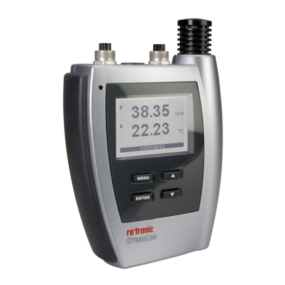
1. Overview
1.1 General
General description of the HygroLog HL-NT data logger and its primary features.
1.2 Compatibility with previous models of probes and docking stations
Details compatibility of the HygroLog HL-NT with older probes and docking stations.
2. General description of the HygroLog HL-NT
2.1 Models
Lists and describes the different HygroLog HL-NT models available.
2.2 Required accessories
Lists accessories necessary for the operation of the HygroLog HL-NT.
2.3 HygroLog HL-NT inputs
Details the types of probes and external connections the logger supports.
2.3.2 Probe inputs 2 and 3 (HygroLog HL-NT3)
Describes the additional probe inputs available on the HygroLog HL-NT3.
2.3.3 Connector identification
Diagrams and labels for the logger's input connectors.
2.4 Power supply
2.4.1 Battery lifetime
Details the expected battery life under various operating conditions.
2.4.2 Battery replacement
Instructions on how to replace the battery in the HygroLog HL-NT.
2.8 HygroLog HL-NT functions
2.8.1 Calculated parameter
Lists psychrometric parameters that can be calculated by the logger.
2.8.2 Data logging
Explains the process of data logging, file formats, and settings.
2.8.3 Trend indicators
Describes the visual indicators for rising, falling, or stable measured values.
2.8.4 Alarm function
Details how to set and manage high and low alarm values for parameters.
2.8.5 Display-Sleep function
Explains how the display sleep function conserves battery power.
2.9 HygroClip 2 probe functions
2.9.1 Simulator function (validation of the signal transmission)
Function to validate probe signal transmission using simulated data.
2.9.2 Sensor failure detection and fail safe mode
How the probe detects sensor failures and enters a fail-safe mode.
3. Docking stations for the HygroLog HL-NT
3.1 Models
Overview of the different docking station models and their configurations.
3.3 Docking station inputs
3.3.1 HygroClip 2 probes
Configuration of docking station inputs for HygroClip 2 probes.
3.3.2 1-channel analog probes with voltage output
Connecting analog probes with voltage output to docking station inputs.
3.3.3 1-channel analog probes with current output
Connecting analog probes with 4-20mA current output.
3.3.4 Pt100 RTD 4-wire probes
Connecting Pt100 RTD probes to docking stations.
3.3.5 Logical inputs (on / off)
Using logical inputs to monitor external contacts like doors or relays.
4. Pin-out diagrams
4.1 HygroLog HL-NT2 and HL-NT3
Pin-out for the probe inputs on HygroLog HL-NT2 and HL-NT3 loggers.
4.2 Docking stations HL-DS-U1, HLDS--U2, HL-DS-U4, HL-DS-U4-420 and HL-DS-U4-WL
Pin-out diagrams for various USB and Ethernet docking stations.
4.3 Docking stations HL-DS-PT2, HL-DS-PT4 and HL-DS-PT4-WL: direct Pt100 RTD
Pin-out for docking stations supporting Pt100 RTD probes.
4.4 Docking stations with logical inputs
Pin-out for docking stations with logical input connectors.
4.5 Docking station HL-DS-R1 with relay outputs
Pin-out for the HL-DS-R1 docking station with relay outputs.
4.6 Docking stations with RS-485 port
Pin-out for docking stations with RS-485 communication ports.
4.7 Docking stations with RS-232 port
Pin-out for docking stations with RS-232 communication ports.
5. HW4 software
5.1 Computer/Operating System Requirements
Minimum hardware and OS requirements for installing and running HW4 software.
5.2 Operating System Compatibility
Lists the operating systems compatible with the HW4 software.
5.3 Settings and functions accessible only with HW4
Details device settings and functions configurable exclusively through the HW4 software.
8. Stand-alone operation
8.1 Operating modes
Describes the two main operating modes: Measure and Record.
8.2 Display and keypad
Details the logger's display characteristics and keypad functions.
8.5 Internal function menu (models with display and keypad)
8.5.1 Log data
Instructions for starting and stopping data logging directly from the logger's menu.
8.5.2 View data
How to view recorded data from the most recent log file on the logger's display.
8.5.3 Adjust
Procedure for performing a 1-point adjustment on connected HygroClip 2 probes.
8.5.4 Settings
Allows reviewing and modifying logger settings like units, display, date, and time.
8.5.5 Instrument
Displays information about the logger's firmware, serial number, and battery status.
8.5.6 Inputs
Provides status and configuration details for logger and docking station inputs.
8.5.7 Docking station
Shows status and firmware information for an attached docking station.
9. Operation on a network
9.1 Baud rate and communications protocol compatibility requirements
Ensures compatibility by setting correct baud rates and communication protocols.
9.2 Ethernet local area network
Information on configuring and connecting the logger to an Ethernet LAN.
9.3 RS-485 multi-drop network
Instructions for connecting multiple devices using the RS-485 multi-drop network.
10. HygroClip probe adjustment procedures
10.1 Single Point adjustment
Procedure for performing a single-point offset adjustment on a probe.
10.2 Multi-Point adjustment
Describes the multi-point adjustment function available via HW4 software.
Need help?
Do you have a question about the HygroLog HL-NT3 and is the answer not in the manual?
Questions and answers