Sign In
Upload
Download
Table of Contents
Contents
Add to my manuals
Delete from my manuals
Share
URL of this page:
HTML Link:
Bookmark this page
Add
Manual will be automatically added to "My Manuals"
Print this page
×
Bookmark added
×
Added to my manuals
Manuals
Brands
Rotronic Manuals
Other
HygroLog HL-NT2
Instruction manual
Rotronic HygroLog HL-NT2 Instruction Manual
Hygrolog hl-nt series
Hide thumbs
1
Table Of Contents
2
3
4
5
6
7
8
9
10
11
12
13
14
15
16
17
18
19
20
21
22
23
24
25
26
27
28
29
30
31
32
33
34
35
36
37
38
39
40
41
42
43
44
45
46
47
48
page
of
48
Go
/
48
Contents
Table of Contents
Bookmarks
Table of Contents
Table of Contents
1 Overview
General
IN-E-HL-NT-V2_12 Rotronic AG
Compatibility with Previous Models of Probes and Docking Stations
2 General Description of the Hygrolog HL-NT
Hygrolog HL-NT Inputs
Models
Required Accessories
Power Supply
Memory Card
Beeper
Hygrolog HL-NT Functions
LED Indicators
Hygroclip 2 Probe Functions
Event Tracking
Operating Limits (Electronics Only)
3 Docking Stations for the Hygrolog HL-NT
Models
Installation
Docking Station Inputs
4 Pin-Out Diagrams
Relay Contacts
Computer/Operating System Requirements
5 HW4 Software
Operating System Compatibility
Settings and Functions Accessible Only with HW4
6 ERES Regulatory Compliance
Display and Keypad
7 Getting Started
Operating Modes
8 Stand-Alone Operation
Display Modes
Settings and Functions Accessible from the Keypad
Internal Function Menu (Models with Display and Keypad)
Baud Rate and Communications Protocol Compatibility Requirements
Ethernet Local Area Network
9 Operation on a Network
RS-485 Multi-Drop Network
General Wiring Guidelines
Guidelines for RS-485 Wiring
10 Hygroclip Probe Adjustment Procedures
Single Point Adjustment
Multi-Point Adjustment
11 Warnings and Useful Tips
12 Communications Protocol
13 Firmware Updates
14 Specifications
15 Accessories
16 Supporting Documents
17 Document Releases
Advertisement
Quick Links
1
General
2
Power Supply
3
Specifications
Download this manual
IN-E-HL-NT-V2_12
Document code
HygroLog HL-NT data logger:
instruction manual
Document title
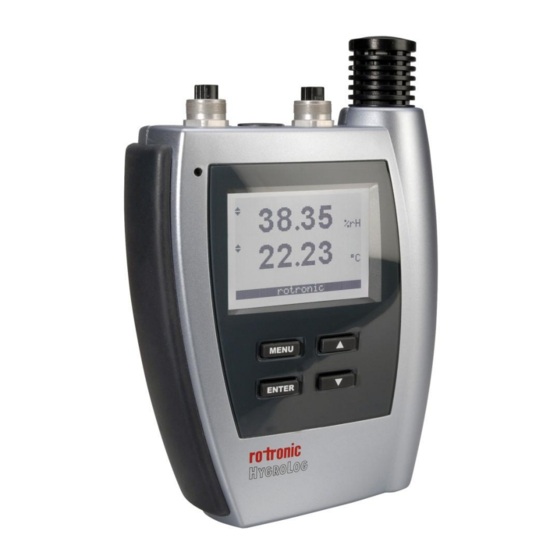
HygroLog HL-NT Data Logger
© 2009-2012; Rotronic AG
Instruction Manual
Rotronic AG
Bassersdorf, Switzerland
Unit
Instruction Manual
Page
1 of 48
IN-E-HL-NT-V2_12
Document Type
Table of
Contents
Previous
Page
Next
Page
1
2
3
4
5
Advertisement
Table of Contents
Need help?
Do you have a question about the HygroLog HL-NT2 and is the answer not in the manual?
Ask a question
Questions and answers
Related Manuals for Rotronic HygroLog HL-NT2
Rotronic HL-1D Short Instruction Manual
Data logger for humidity and temperature (4 pages)
Rotronic HygroLog HL-NT3 Instruction Manual
Hygrolog hl-nt series (48 pages)
Rotronic HygroLog HL-NT3-D Instruction Manual
Hygrolog hl-nt series (48 pages)
This manual is also suitable for:
Hygrolog hl-nt2-d
Hygrolog hl-nt3
Hygrolog hl-nt3-d
Hygrolog hl-nt3-p
Hygrolog hl-nt3-dp
Hygrolog hl-nt2-dp
...
Show all
Hygrolog hl-nt2-p
Table of Contents
Print
Rename the bookmark
Delete bookmark?
Delete from my manuals?
Login
Sign In
OR
Sign in with Facebook
Sign in with Google
Upload manual
Upload from disk
Upload from URL


Need help?
Do you have a question about the HygroLog HL-NT2 and is the answer not in the manual?
Questions and answers