Table of Contents
Advertisement
Advertisement
Table of Contents

Related Manuals for Cardiac Science TM55


Summarization of Contents
Safety
Safety Terms and Definitions
Defines hazard categories using symbols: WARNING for serious injury/death, CAUTION for minor injury/damage.
Warnings and Cautions
Provides essential warnings and cautions for safe operation and setup of the treadmill.
Safety Notes
Details equipment classification, operating guidelines, and safety recommendations.
Symbol Definitions
Explains various symbols and warning labels found on the treadmill for user protection.
EMC Declaration Tables
Lists electromagnetic compatibility (EMC) declarations, including emissions and immunity guidelines.
Introduction
Controls
Describes the operation, power, and emergency stop button functions of the treadmill.
Indicators
States that there are no visual indicators on the treadmill; all feedback is on the stress monitor.
Installation
Refers to the User Guide for complete treadmill installation procedures and site requirements.
Theory of Operation
Overview
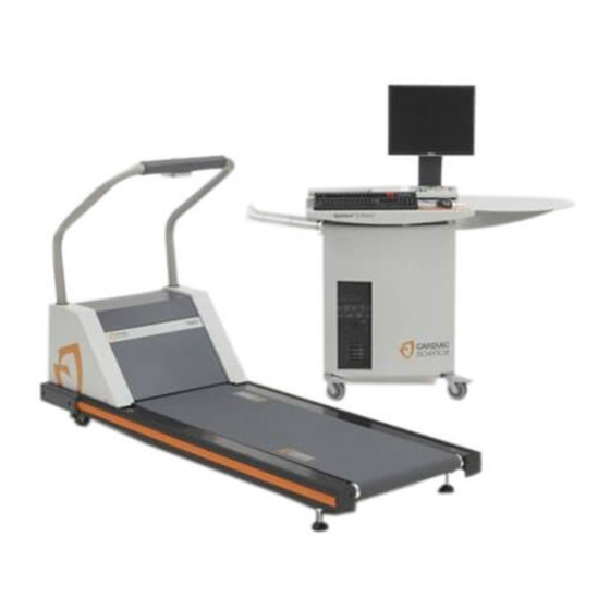
Explains the treadmill's two subassemblies and the stress monitor's role as the user interface.
Headframe Assembly
Details the headframe's function in receiving commands and housing drive/grade systems.
Deck and Roller Assembly
Describes the deck and roller assembly as the walking platform and belt support.
Stress Monitor to Treadmill Interface
Explains communication interfaces (RS232 for TM, RS422 for ST) with the stress monitor.
Preventative Maintenance
Recommended Service
Specifies that routine service is necessary every six months for repairs at the modular level.
Routine Maintenance
Outlines visual inspection, cleaning, and disinfection procedures for treadmill upkeep.
Vacuuming Under the Treadmill Hood
Details procedures for vacuuming internal components to maintain airflow and prevent overheating.
Replacement Schedules
Recommends replacing belts if they show signs of fraying or excessive wear.
Electrical Testing
Instructs on periodic electrical testing, including leakage current checks, by facility biomedical departments.
Repair/Replacement and Calibration
Electrical Shock Safety
Highlights high voltage hazards and safety precautions before working on the treadmill.
Mechanical Hazards
Addresses risks like moving parts, sharp edges, and improper lifting during maintenance.
Tools Required for Repair
Lists essential tools for performing repairs and replacements on the treadmill.
Removing the Treadmill Hood
Provides step-by-step instructions for safely removing the treadmill's protective hood.
Replacing the AC Drive Module
Details the procedure for replacing the AC Drive Module as a complete unit.
Replacing the Drive Motor
Guides on how to replace the drive motor, including alignment of pulleys.
Replacing the Grade Motor
Explains the process for replacing the grade motor and verifying its operation.
Replacing the Walking Belt
Provides instructions for removing and installing a new walking belt on the treadmill.
Adjusting the Walking Belt
Details methods for adjusting belt tension and tracking for optimal performance.
Calibration Procedures
Describes how to calibrate the grade potentiometer for accurate grade adjustments.
Troubleshooting
Diagnosis and Problem Identification
Outlines common electrical, electronic, and mechanical problems and diagnostic approaches.
Tools for Troubleshooting
Lists necessary tools, including safety precautions for electrical and mechanical issues.
Electrical Problems
Addresses issues like the treadmill not starting, circuit breaker trips, and power cord problems.
Electronic Problems and Error Codes
Explains how error codes are used for diagnostics and troubleshooting electronic issues.
Mechanical Problems
Covers noise and vibration issues related to belts, motors, and other mechanical parts.
Error Flow Charts
Provides flow charts for step-by-step troubleshooting of specific error codes and problems.
Specifications
Cardiac Stress Treadmills Specifications
Lists performance, physical, and environmental specifications for the treadmills.
Power Requirements
Details the nominal voltage range, current draw, and minimum branch circuit amps needed.
Speed vs. Weight Range
Presents a performance envelope graph showing speed limits based on user weight.
Part Numbers
Final Assemblies
Instructs to refer to the name plate for part numbers of treadmill assemblies.
Spares Inventory
Lists spare parts categorized by electrical, drive, and grade systems with their part numbers.
Placement of Spare Parts
Shows diagrams illustrating the location of various spare parts on the treadmill.
Drawings
Wiring Diagrams Overview
Indicates that wiring diagrams for low and high voltage models are provided.
Diagrams
Wiring Diagram, Low Voltage Treadmill
Presents the detailed wiring schematic for the low voltage treadmill model.
Wiring Diagram, High Voltage Treadmill
Presents the detailed wiring schematic for the high voltage treadmill model.
Need help?
Do you have a question about the TM55 and is the answer not in the manual?
Questions and answers