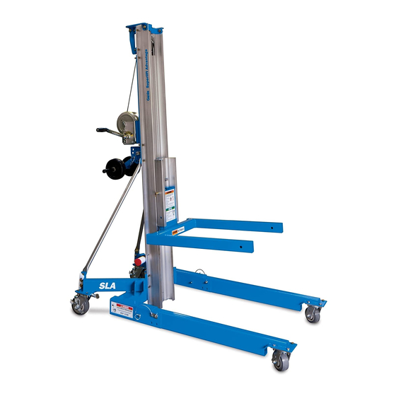
Table of Contents
Advertisement
Advertisement
Table of Contents

Summarization of Contents
Section 3: Scheduled Maintenance Inspections
Maintenance Schedule Overview
Outlines the schedule for daily, quarterly, and annual maintenance inspections.
Maintenance Tables Explained
Explains the content and purpose of maintenance tables.
Maintenance Inspection Report Details
Details the maintenance inspection report and record-keeping requirements.
Section 4: Scheduled Maintenance Procedures
Daily Maintenance Procedures (Table A)
Details step-by-step procedures for daily maintenance inspections.
Quarterly Maintenance Procedures (Table B)
Details step-by-step procedures for quarterly maintenance inspections.
Annual Maintenance Procedures (Table C)
Details step-by-step procedures for annual maintenance inspections.
Section 5: Troubleshooting Flow Charts
Troubleshooting: Mast Sequencing Issues
Troubleshooting guide for issues with mast sequencing.
Troubleshooting: Carriage Not Raising
Troubleshooting guide for carriage not raising but winch operating.
Troubleshooting: Winch Not Operating
Troubleshooting guide for winch not operating issues.
Section 6: Repair Procedures
Base Assembly Repair Procedures
Procedures for removing and servicing the base of the machine.
Mast Assembly Repair Procedures
Procedures for disassembling and assembling the mast.
Winch Repair Procedures
Procedures for disassembling and assembling winches.
Section 7: Service Parts
Ordering Replacement Parts
Instructions and information required for ordering replacement parts.
Decals and Paint (Figure 7-A)
Illustrates decals and paint components for the Superlift.
Standard Base Components (Figure 7-C)
Illustrates and lists components for the standard base assembly.
Mast Components View 1 (Figure 7-E)
Illustrates mast components and their parts.
Single Speed Winch Diagram (Figure 7-L)
Exploded view of the single-speed winch assembly.


Need help?
Do you have a question about the Superlift SL-25 and is the answer not in the manual?
Questions and answers