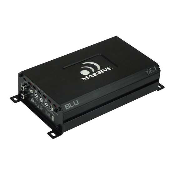
Summary of Contents for Massive BL3
- Page 1 Nano Blu Amplifier Dura-Coated Epoxy 320° Marine Grade PCB High Temp & Humidity 2 2 2 2...
- Page 2 INTRODUCTION Congratulations! And thank you for purchasing a "Massive Audio" Nano Blu amplifier for your car audio system. You now own an amplifier of uncompromising design and engineering incorporating the latest advances in micro topology. This handcrafted amplifier is designed to deliver the demands of serious sound competitors.
-
Page 3: Design Features
Extreme power in a mini compact footprint Conformal Coated PC Board to Resist Moisture, Dust and Extreme Heat 1 Ohm stable design (BL1,BL3) 4 Layers PCB design with SMD parts Built-in noise reduction circuitry Full MOSFET with high grade switching devices... -
Page 4: Amplifier Functions
This control is used to select the desired low pass x-over frequency. The frequency can be adjusted from 5OHz to 150Hz(BL2) & 4OHz to 200Hz(BLX5). 9. Low Pass Filter Control(BL1,BL3,BLX5) This control can filted out unwanted low frequency from 15Hz to 40Hz. -
Page 5: Panel Layout
Set this switch to conjunction with how many input cables being used. In the 2 channel setting all four output will be activated. 19. Line Out(BLX2,BLX4,BLX48) This “Full range output” can be connected to any additional amplifier. (Example: separate subwoofer amplifier) PANEL LAYOUT Fig 1. BL1/BL3 amplifier panel layout... - Page 6 PANEL LAYOUT Fig 2.BLX2 amplifier panel layout...
- Page 7 PANEL LAYOUT Fig 3.BLX4/BLX48 amplifier panel layout PANEL LAYOUT Fig 4.BLX5 amplifier panel layout...
-
Page 8: Wiring Diagram
Fig 5. BLX4/BLX48 amplifier wiring (Multi-woofer load) Wiring Diagram Fig 6. BL1/BL3 amplifier wiring (SINGLE WOOFER LOAD) Equivalent parallel woofer loads cannot be less than the minimum stable load rated in this manual. The two negative and two positive speaker terminals are wired internally inside each amplifier. - Page 9 Wiring Diagram Fig 7. BL1 AMPLIFIER WIRING (1-CHANNEL MODE) Wiring Diagram Fig 8. BL3 AMPLIFIER WIRING (1-CHANNEL MODE)
- Page 10 Wiring Diagram Fig 9. BLX2 AMPLIFIER WIRING (1-CHANNEL MODE) 2 OHM MINIMUM Wiring Diagram Fig 10. BLX2 AMPLIFIER WIRING (2-CHANNEL MODE) 2OHM-4OHM 2OHM-4OHM...
- Page 11 Wiring Diagram Fig 11. BLX4 BLX48 AMPLIFIER WIRING (3-CHANNEL MODE) 2OHM-4OHM 2OHM-4OHM...
- Page 12 Wiring Diagram Fig 12. BLX4 BLX48 AMPLIFIER WIRING (4-CHANNEL MODE) 2OHM-4OHM 2OHM-4OHM 2OHM-4OHM 2OHM-4OHM...
- Page 13 Wiring Diagram Fig 13. BLX5 AMPLIFIER WIRING (5-CHANNEL MODE) 2OHM-4OHM 2OHM-4OHM 2 OHM MINIMUM 2OHM-4OHM 2OHM-4OHM AUTOMATIC SIGNALS AUTOMATIC SIGNALS...
-
Page 14: Troubleshooting
Trouble Shooting... -
Page 15: Specifications
Specifications... -
Page 16: Warranty
“Massive Audio” dealer. Units that are not installed by an authorized “Massive Audio” dealer maintain a warranty not to exceed 90 days from the original purchase date by the original purchaser. ducts that display abuse such as power deficiency, over driving the amplifier or clipping the input require purchase of a new PCB for replacement. - Page 17 0040 U.S.A. Copyright 2017 Massive Audio ,Inc. USA Due to constant Improvements all designs and specifications are subject to change without notice. V170503...


Need help?
Do you have a question about the BL3 and is the answer not in the manual?
Questions and answers