Table of Contents
Advertisement
Advertisement
Table of Contents

Related Manuals for Niko Home Control


Summarization of Contents
1. Installation Preparations
Bus Cable Guidelines
Guidelines for selecting bus cable diameter and laying.
Control Point Guidelines
Guidelines for installing push buttons, displays, and motion detectors.
2. Controller
Description
Explains the controller's function in the Niko Home Control system.
Overview
Visual guide to the controller's ports, LEDs, and buttons.
3. Power Supply
Description
Details the function of the power supply module for the installation.
Overview
Identifies the components and terminals of the power supply module.
4. Rail Coupler
Description
Explains the rail coupler's role in interconnecting modules.
Overview
Shows the rail coupler and its connection points.
Installation
Step-by-step guide for mounting and connecting the rail coupler.
5. Wall-Mounted Printed Circuit Boards and Push Buttons
5.1. Wall-Mounted Printed Circuit Boards
Describes the function and types of printed circuit boards for push buttons.
6. Push Buttons with Display
Description
Introduces mood setting, thermostat, and eco-display push buttons.
Installation
Instructions for mounting push buttons with displays.
7. Switching Modules
Description
Explains the function of three-fold and six-fold switching modules.
Overview
Shows the switching module's terminals and LEDs.
8. Universal Dimming Module
Description
Details the module for dimming light circuits with two channels.
Overview
Illustrates the dimming module's components and connections.
9. Electricity Measuring Modules
Description
Explains modules for measuring energy consumption and production.
Overview
Shows the electricity measuring modules and their current clamps.
10. Pulse Counter
Description
Describes the module for monitoring gas, water, and electricity consumption.
Overview
Displays the pulse counter module and its terminals.
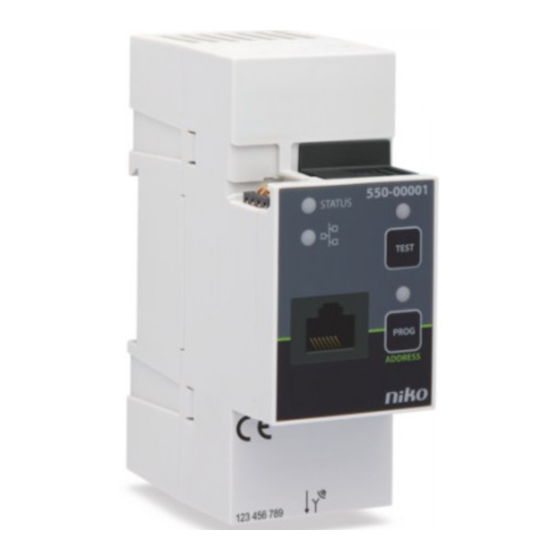
11. IP Interface
Description
Explains how the IP interface connects the system to a local IP network.
Overview
Shows the IP interface, its ports, and LEDs.
12. Gateway
Description
Details the gateway for connecting the installation to the internet.
Overview
Illustrates the gateway's ports and status LEDs.
13. Touchscreen
Description
Describes the user-friendly interface for operating the installation.
Overview
Shows the touchscreen display and its main sections.
14. Indoor Motion Detector
Description
Explains the motion detector's function in activating/deactivating functions.
Overview
Displays the indoor motion detector components.
15. Outdoor Motion Detector
Description
Details the outdoor motion detector for detecting motion and light.
Overview
Shows the outdoor motion detector and its parts.
16. Ventilation Module
Description
Explains the module for controlling central ventilation systems.
Overview
Illustrates the ventilation module's terminals and LEDs.
17. Heating or Cooling Module
Description
Describes the module for controlling heating or cooling in four zones.
Overview
Shows the heating/cooling module's terminals and LEDs.
18. Motor Module
Description
Explains the module for operating motor-controlled applications like shutters.
Overview
Displays the motor module's terminals and buttons.
19. Analogue Sensor Module
Description
Details the module for connecting external analogue sensors.
Overview
Shows the analogue sensor module and its connection terminals.
20. Digital Potential-Free Sensor Module
Description
Explains the module for connecting digital potential-free sensors.
Overview
Illustrates the digital sensor module and its terminals.
21. Analogue Control Module 0-10 V
Description
Describes the module for connecting high-power dimmers with 0-10 V input.
Overview
Shows the analogue control module and its connection terminals.
22. Analogue Control Module 1-10 V
Description
Details the module for connecting dimmers/devices with 1-10 V input.
Overview
Displays the analogue control module and its terminals.
23. Push-Button Interface
Description
Explains the interface for connecting push buttons and transistor outputs.
Overview
Shows the push-button interface and its connection wires.
24. Nikobus Interface
Description
Describes the interface for expanding Nikobus installations with Niko Home Control functions.
Overview
Illustrates the Nikobus interface and its terminals.
25. RF Interface Easywave
Description
Explains the interface for using Niko wireless Easywave controls.
Overview
Shows the RF interface, its antenna, and status LEDs.
Need help?
Do you have a question about the Home Control and is the answer not in the manual?
Questions and answers