Advertisement
Quick Links
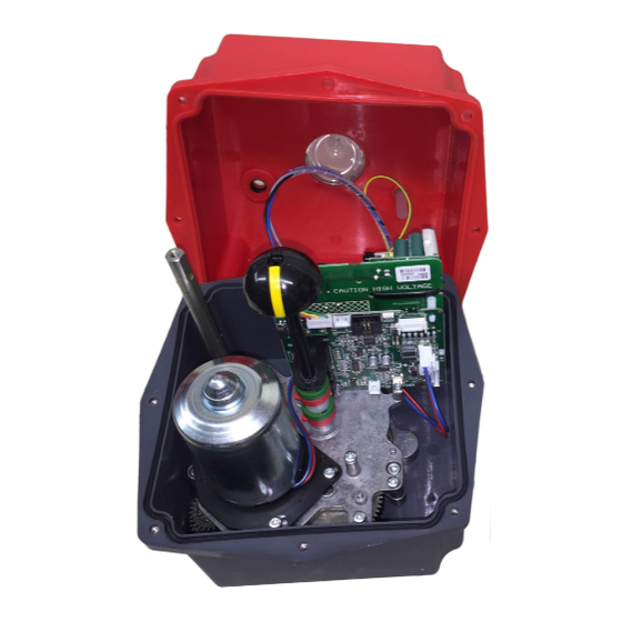
J3C
Electric Valve Actuator
Models 140 & 300
FAILSAFE AND/ OR MODULATING FUNCTION CONVERSION
J3C
FAILSAFE ACTUATOR
WITH BSR PLUG & PLAY KIT OPTION
J3C
MODULATING ACTUATOR
WITH DPS PLUG & PLAY KIT OPTION
Installation Instructions for FAILSAFE and/or MODULATING
plug and play function conversion kits
J3C140PPK-A4-IOM-MAIN-Rev 1-Aug 17
Advertisement

Related Manuals for J3C H300


Summarization of Contents
What is the BSR Failsafe Conversion Kit?
How the BSR System Works
Details the operational mechanism of the BSR plug and play failsafe kit.
J3C-140/300 BSR Kit Contents
Lists the components included in the J3C-140/300 BSR kit, such as batteries and PCB.
J3C-140/300 BSR Safety & Warranty Instructions
Safety Instructions
Emphasizes the need for qualified personnel and independent power supplies for safety.
Warranty Information
Details the 12-month warranty against defects and conditions for validity.
J3C-140/300 BSR Installation for Failsafe Functionality
Step 1: Prepare for Battery Installation
Remove actuator cover and identify mounting pegs for the first battery.
Step 2: Mount First Battery
Mount the first battery and secure it, identifying pegs for the second battery.
Step 3: Mount Second Battery
Prepare and mount the second battery pack using provided screws and washers.
J3C-140/300 BSR Installation for Failsafe Functionality
Step 4: Install Circuit Board
Install the BSR printed circuit board, ensuring secure connections and fastening.
Step 5: Configure Fail Position
Install the jumper for 'fail closed' or omit for 'fail open' function.
J3C-140/300 BSR Specifications
LED Sequences with BSR Battery Backup
Explains the LED indicator sequences for various actuator states with BSR installed.
J3C-140/300 DPS Installation for Modulating Function
Step 1: Prepare Mounting Column
Set actuator to CLOSED and screw in the DPS circuit board support column.
Step 2: Mount DPS Circuit Board
Slide DPS circuit board onto shaft, aligning spigot and ensuring plug connection.
Step 3: Secure DPS PCB
Secure the DPS PCB with a screw into the support column.
J3C-140/300 DPS Installation for Modulating Function
Step 4: Reconnect and Configure
Replace cover, reconnect power, and connect control signal to DPS PCB.
J3C-140/300 DPS Specifications
LED Sequences with DPS Positioner Installed
Explains LED indicator sequences for various actuator states with DPS installed.
Wiring Diagrams
J3C On-Off Actuator Wiring
Describes wiring for the standard ON-OFF electric actuator function.
J3C Failsafe Actuator Wiring
Explains wiring for the failsafe function on loss of external power.
J3C Modulating Actuator Wiring
Details wiring for the modulating function controlled by an input signal.
J3C Failsafe Modulating Actuator Wiring
Covers wiring for combined failsafe and modulating functions.
Important Notes on Power and Signals
Crucial information on power supply, condensation, and signal switching.
Mounting the J3C Actuator to 1/4 Turn Valves
Mounting Orientation Guidelines
Specifies correct and prohibited mounting orientations for the actuator.
Weatherproof Rating and Protection
Explains the IP67 rating and precautions against water ingress.
End of Life Recycle and Disposal
Advises on responsible disposal and recycling of the actuator.
Technical Support Contact
Provides contact information for live technical support.
Need help?
Do you have a question about the H300 and is the answer not in the manual?
Questions and answers