Advertisement
Quick Links
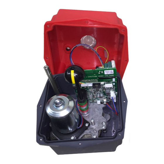
J3C
Electric Valve Actuator
Models 140 & 300
FAILSAFE AND/ OR MODULATING FUNCTION CONVERSION
J3C
FAILSAFE ACTUATOR
WITH BSR PLUG & PLAY KIT OPTION
J3C
MODULATING ACTUATOR
WITH DPS PLUG & PLAY KIT OPTION
Installation Instructions for FAILSAFE and/or MODULATING
plug and play function conversion kits
J3C140PPK-A4-IOM-MAIN-Rev 1-Aug 17
Advertisement


Need help?
Do you have a question about the H140 and is the answer not in the manual?
Questions and answers