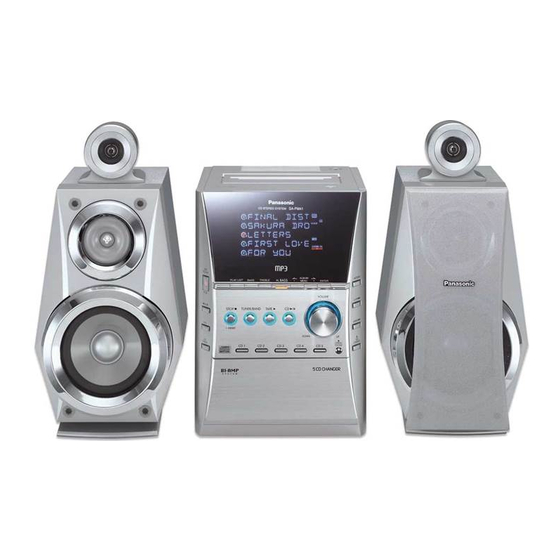
Panasonic SB-PM41 Service Manual
Hide thumbs
Also See for SB-PM41:
- Operating instructions manual (20 pages) ,
- Operating instructions manual (20 pages)
Table of Contents
Advertisement
Specification
n Amplifier Section
Power output
10%, Total harmonic distortion
60 Hz-3 kHz, both channels driven
(Low channel)
3 kHz-16 kHz, both channels driven
(High channel)
Total Bi-Amp power
Power output
10% Total harmonic distortion
1 kHz, both channels driven
(Low channel)
8 kHz, both channels driven
(High channel)
Total Bi-Amp power
Output Impedance
Headphone
n FM Tuner Section
Frequency range
Sensitivity
S/N 26dB
Antenna terminal(s)
n AM Tuner Section
Frequency range
26 W per channel (6 Ω)
29 W per channel (6 Ω)
55 W per channel
35 W per channel (6 Ω)
35 W per channel (6 Ω)
70 W per channel
16Ω - 32 Ω
87.5 MHz - 108.0 MHz
(100 kHz steps)
87.9 MHz - 107.9 MHz
(200 kHz steps)
1.5 µV (IHF)
1.5 µV
75 Ω (unbalanced)
520kHz - 1710 kHz (10kHz steps)
SA-PM41P
SA-PM41PC
Colour
(S)... Silver Type
Sensitivity
S/N 20 dB (at 1000 kHz)
n Cassette Deck Section
Track system
Heads
Record/playback
Erasure
Motor
Recording system
Erasing system
Tape speed
Overall frequency response (+3 dB, -6 dB) at DECK OUT)
NORMAL (TYPE I)
S/N RATIO
Wow and flutter
Fast forward and rewind time
n CD Section
Disc
CD, CD-R, CD-RW, MP3
Sampling frequency
Decoding
Beam source / wavelength
Number of channels
Frequency response
Wow and flutter
Digital filter
© 2005 Matsushita Electric Industrial Co. Ltd.. All
rights
reserved.
distribution is a violation of law.
ORDER NO. MD0501004C1
CD Stereo System
560 µV/m
4 track, 2 channel
Solid permalloy head
Double gap ferrite head
DC servo motor
AC bias 100 kHz
AC erase 100 kHz
35 Hz - 14 kHz
45dB (A weighted)
0.10% (WRMS)
Approx. 120 seconds with C-60
cassette tape
3
8cm / 12cm (3
/
" / 4
20
44.1 kHz
16 bit linear
Semiconductor laser / 780 nm
20 Hz - 20 kHz (+1dB, -2 dB)
Below measurable limit
Unauthorized
copying
A6
4.8 cm/s
73
/
")
100
Stereo
8 fs
and
Advertisement
Table of Contents

Related Manuals for Panasonic SB-PM41


Summarization of Contents
Specification
Amplifier Section
Details on output power, harmonic distortion, and impedance.
Cassette Deck Section
Specifications for track system, heads, frequency response, S/N, and wow/flutter.
CD Section
Details on compatible disc types, sampling frequency, decoding, and laser.
Safety Precautions
General Guidelines
General safety rules for servicing and handling the unit.
Leakage Current Checks
Procedures for checking electrical safety via cold and hot methods.
Caution for Fuse Replacement
Specific safety warning regarding fuse replacement.
Handling the Lead-free Solder
About Lead-Free Solder (PbF)
Identifying and handling lead-free solder and related PCBs.
Handling Precautions For Traverse Deck
Handling of Traverse Deck (Optical Pickup)
Precautions for static electricity when handling the optical pickup.
Grounding for Electrostatic Breakdown Prevention
Steps to prevent static discharge during servicing.
Assembling and Disassembling
Disassembly Flow Chart
Overview of the component disassembly process.
External Component Disassembly
Guide to removing side panels and cabinets.
Internal PCB Disassembly
Steps to access main circuit boards for removal.
Mechanism Component Replacement
Procedures for replacing cassette and other mechanisms.
Service Positions
Checking Procedure
General notes and guidelines for service checks.
Checking the Major P.C.B
Identifying main printed circuit boards for inspection.
Self-Diagnostic Display Function
Diagnostic Modes and Operations
Covers entering, clearing, displaying, and checking diagnostic modes.
Error Code Table
List of error codes and their potential causes.
Procedure for Checking Operation of Individual Parts of Cassette Mechanism Unit
Operation Check with Cassette Tape
Testing cassette mechanism functionality with a tape.
Operation Check without Cassette Tape
Testing cassette mechanism functionality without a tape.
Measurement And Adjustments
Cassette Deck Section
Requirements and settings for cassette deck measurements.
Voltage Measurement
Measuring voltage levels across various PCBs.
Block Diagram
CD SERVO Block
Diagram illustrating the CD servo circuit.
MAIN Block
Diagram illustrating the main processing unit.
Schematic Diagram
CD SERVO CIRCUIT
Electrical schematic for the CD servo system.
MAIN CIRCUIT
Electrical schematic for the main unit's circuitry.
Major System Schematics
Schematics for control, power, and function circuits.
Printed Circuit Board Layouts
CD SERVO and Main P.C.B. Layouts
Component placement diagrams for CD servo and main boards.
Control, Power, and Deck P.C.B. Layouts
Component placement diagrams for control, power, and deck boards.
Terminal Function of IC’s
IC302 Microprocessor Terminal Functions
Pin functions and descriptions for the microprocessor IC.
IC702 Servo Processor Terminal Functions
Pin functions for the servo processor IC.
IC703 4CH Drive IC Terminal Functions
Pin functions for the 4-channel drive IC.
Parts Lists and Locations
Deck Mechanism Parts
Location and list of deck mechanism components.
CD Loading Mechanism Parts
Location and list of CD loading mechanism components.
Cabinet and Electrical Parts Lists
Lists for cabinet parts and all electrical components.
Packaging & Accessories
List of packing materials and included accessories.
Need help?
Do you have a question about the SB-PM41 and is the answer not in the manual?
Questions and answers