Sign In
Upload
Download
Table of Contents
Contents
Add to my manuals
Delete from my manuals
Share
URL of this page:
HTML Link:
Bookmark this page
Add
Manual will be automatically added to "My Manuals"
Print this page
×
Bookmark added
×
Added to my manuals
Manuals
Brands
Cambium Manuals
Wireless Access Point
PMP 450i AP
User manual
Cambium PMP 450i AP User Manual
450 platform family; 450 series;450i series;450b series;450m series
Hide thumbs
1
2
3
4
5
6
7
8
9
10
11
12
13
14
15
16
17
18
19
20
21
22
23
24
25
26
27
28
29
30
31
32
33
34
35
36
37
38
39
40
41
42
43
44
45
46
47
48
49
50
51
52
53
54
55
56
57
58
59
60
61
62
63
64
65
66
67
68
69
70
71
72
73
74
75
76
77
78
79
80
81
82
83
84
85
86
87
88
89
90
91
92
93
94
95
96
97
98
99
100
101
102
103
104
105
106
107
108
109
110
111
112
113
114
115
116
117
118
119
120
121
122
123
124
125
126
127
128
129
130
131
132
133
134
135
136
137
138
139
140
141
142
143
144
145
146
147
148
149
150
151
152
153
154
155
156
157
158
159
160
161
162
163
164
165
166
167
168
169
170
171
172
173
174
175
176
177
178
179
180
181
182
183
184
185
186
187
188
189
190
191
192
193
194
195
196
197
198
199
200
201
202
203
204
205
206
207
208
209
210
211
212
213
214
215
216
217
218
219
220
221
222
223
224
225
226
227
228
229
230
231
232
233
234
235
236
237
238
239
240
241
242
243
244
245
246
247
248
249
250
251
252
253
254
255
256
257
258
259
260
261
262
263
264
265
266
267
268
269
270
271
272
273
274
275
276
277
278
279
280
281
282
283
284
285
286
287
288
289
290
291
292
293
294
295
296
297
298
299
300
301
page
of
301
Go
/
301
Contents
Table of Contents
Troubleshooting
Bookmarks
Table of Contents
Table of Contents
List of Figures
Alignment Tone
Logs
List of Tables
About this User Guide
Contacting Cambium Networks
Product Notation Conventions in Document
Purpose
Cross References
Feedback
Application Software
Important Regulatory Information
USA Specific Information
Canada Specific Information
Renseignements Specifiques au Canada
Ethernet Networking Skills
EU Declaration of Conformity
Lightning Protection
Specific Expertise and Training for Professional Installers
Training
Hardware Warranty
Problems and Warranty
Repair and Service
Reporting Problems
Security Advice
Cautions
Notes
Warnings
Warnings, Cautions, and Notes
Caring for the Environment
In EU Countries
In Non-EU Countries
Chapter 1: Product Description
Overview of the 450 Platform Family
PMP 450M Series
Purpose
Table 1 Main Characteristics of the PMP 450M Series AP
Table 2 PMP 450M Series Hardware Configurations
PMP/PTP 450I Series
Table 3 Main Characteristics of the PMP/PTP 450I Series
Table 4 PMP/PTP 450I Series Hardware Configurations
Ethernet Interface
PMP 450B Series
Table 5 Main Characteristics of the PMP 450B Series
Table 6 PMP 450B Series Hardware Configurations
PMP/PTP 450 Series
Table 7 Main Characteristics of the PMP/PTP 450 Series
Table 8 PMP/PTP 450 Series Hardware Configurations
Supported Interoperability for 450M/450I/450B/450 Series
Table 10 Supported Interoperability for PTP
Table 9 Supported Interoperability for PMP
Figure 1 PMP/PTP 450 Platform Family Typical Bridge Deployment
Typical Deployment
Product Variants
Wireless Operation
Figure 2 TDD Frame Division
Time Division Duplexing
Table 11 Modulation Levels
Encryption
Mimo
Mu-Mimo
System Management
Management Agent
Web Server
Network Time Protocol (NTP)
Remote Authentication Dial-In User Service (RADIUS)
Wireless Manager (WM)
Cnmaestro
Radio Recovery Mode
Chapter 2: System Hardware
System Components
Point-To-Multipoint (PMP)
Table 12 PMP 450M Series Variants
Table 13 PMP 450I Series Variants
Table 14 PMP 450B Series Variants
Table 15 PMP 450 Series Variants
Backhaul (PTP)
Table 16 PTP 450I Series Variants
Table 17 PTP 450 Series Variants
450 Platform Family Interfaces
Table 18 PMP 450M Series AP Interface Descriptions and Cabling
Figure 3 PMP 450B Series - SM Interfaces
Table 19 PMP/PTP 450I Series - AP/SM/BH Interface Descriptions and Cabling
Figure 4 PMP/PTP 450 Series - AP Interfaces
Table 20 PMP 450B Series - SM Interface Descriptions and Cabling
Figure 5 PMP/PTP 450 Series - SM/BH Interfaces
Table 21 PMP/PTP 450 Series - AP Interface Descriptions and Cabling - 2.4 Ghz and 5 Ghz
Figure 6 PMP/PTP 450 Series - SM/BH Connectorized Interfaces
Figure 7 PMP 450D Series - SM Integrated Dish
Figure 8 PMP 450 Series - SM 3 Ghz Integrated
Figure 9 PTP 450 Series - BHM/BHS
ATEX/HAZLOC Variants
Diagnostic Leds
Figure 10 AP/BHM Diagnostic Leds, Viewed from Unit Front
Table 22 AP/BHM LED Descriptions
Figure 11 AP/BH Diagnostic Leds, Viewed from Unit Front
Table 23 SM/BHS LED Descriptions
Power Supply Options
Table 24 PSU Part Numbers for PMP 450M AP
Table 25 PSU Part Numbers for PMP/PTP 450I Series
Figure 12 AC Power Injector Interfaces
Table 26 AC Power Injector Interface Functions
Figure 13 AC+DC Enhanced Power Injector Interfaces
Table 27 AC+DC Enhanced Power Injector Interface Functions
Figure 14 -48 V DC Power Injector Interfaces
Table 28 -48V DC Power Injector Interfaces
Figure 15 -20 to 32 VDC Power Injector Interfaces
Table 29 -Power Injector Interfaces
Table 30 PSU Part Numbers for PMP 450B SM
Table 31 PSU Part Numbers for PMP/PTP 450 Series
Table 32 -Gigabit Enet Capable Power Supply
Figure 16 Gigabit Enet Capable Power Supply
Lightning Protection
ODU Mounting Brackets & Accessories
Table 33 Accessories Part Numbers
Table 34 Lightning Protection Part Numbers
ODU Interfaces
Figure 17 PMP 450M Series - AP Rear Interfaces
PMP 450M Series AP
Table 35 PMP 450M Series - AP Rear Interfaces
Figure 18 PMP/PTP 450I Series - ODU Rear Interfaces
PMP/PTP 450I
Table 36 PMP/PTP 450I Series - ODU Rear Interfaces
Figure 19 PMP/PTP 450I Series - Connectorized ODU Antenna Interfaces
Figure 20 PMP 450B Series - ODU Rear Interfaces
PMP 450B
Table 37 PMP 450B Series - ODU Rear Interfaces
Cabling
Ethernet Standards and Cable Lengths
Table 38 PSU Drop Cable Length Restrictions
Figure 21 Outdoor Drop Cable
Outdoor Copper Cat5E Ethernet Cable
Table 39 Drop Cable Part Numbers
SFP Module Kits
Table 40 SFP Module Kit Part Numbers
Table 41 Single Mode Optical SFP Interface Per ODU (Part Number C000065L008)
Table 42 Multi-Mode Optical SFP Interface Per ODU (Part Number C000065L009)
Figure 22 Optical SFP Transceiver Module
Figure 23 Long Cable Gland
Aux Port
Main Ethernet Port
Table 43 Main Port Poe Cable Pinout
Table 44 aux Port Poe Cable Pinout
Figure 24 Alignment Tone Cable
Figure 25 RJ12 Alignment Tone Cable
Table 45 aux Port Poe Cable Pinout
Figure 26 Cable Gland (Part Number #N000065L033)
Table 46 RJ12 aux Port Poe Cable Pinout
Table 47 Alignment Tone Adapter Third Party Product Details
Table 48 RJ45 Connector and Spare Gland Part Numbers
Lightning Protection Unit (LPU) and Grounding Kit
Table 49 LPU and Grounding Kit Contents
Cable Grounding Kit
Figure 27 Cable Grounding Kit
Table 50 LPU and Grounding Kit Part Number
Table 51 Cable Grounding Kit Part Numbers
Antennas and Antenna Cabling
Antenna Requirements
Supported External AP Antennas
Supported External BH/SM Antenna
Table 52 List of AP External Antennas
Table 53 PTP 450I Series BH or PMP 450/450I Series SM External Antenna
Antenna Accessories
RF Cable and Connectors
Table 54 RF Cable and Connector Part Numbers
GPS Synchronization
GPS Synchronization Description
Universal GPS (UGPS)
Cmm5
CMM5 Controller Module
Figure 31 Controller Module
CMM5 Injector Compatibility Matrix
CMM5 Injector Module
Figure 32 Injector Module
Table 57 Injector Compatibility Matrix
CMM5 Specifications
Table 58 CMM5 Specifications
CMM4 (Rack Mount)
Figure 33 CMM4 (Rack Mount)
Figure 35 CMM4 Power Adapter Cabling Diagram
Table 59 CMM4 Power Adapter Cable Pinout
CMM4 (Cabinet with Switch)
CMM4 (Cabinet Without Switch)
Figure 36 CMM4 (Cabinet with Switch)
Cmm3/Cmmmicro
Figure 37 CMM3
Installing a GPS Receiver
GPS Receiver Location
Figure 39 GPS Antenna Mounting
Mounting the GPS Receiver
Cabling the GPS Antenna
Installing and Connecting the GPS LPU
Ordering the Components
Table 60 PMP 450M Series ODU Part Numbers
Table 61 PMP 450I Series ODU Part Numbers
Table 62 PMP 450I ATEX/HAZLOC ODU Models/Part Numbers
Table 63 PTP 450I Series ODU Part Numbers
Table 64 PTP 450I ATEX/HAZLOC ODU Models/Part Numbers
Table 65 PMP 450B Series ODU Part Numbers
Table 66 PMP 450 Series ODU Part Numbers
Table 67 PTP 450 Series ODU Part Numbers
Table 68 PMP/PTP 450/450I Series Accessories
Chapter 3: System Planning
Typical Deployment
Figure 40 Mast or Tower Installation
ODU with Poe Interface to PSU
Figure 41 Wall Installation
Figure 42 Roof Installation
Figure 43 GPS Receiver Wall Installation
Figure 44 GPS Receiver Tower or Mast Installation
Site Planning
Site Selection for PMP/PTP Radios
Grounding and Lightning Protection
Maximum Cable Lengths
Power Supply Site Selection
Figure 45 Rolling Sphere Method to Determine the Lightning Protection Zones
ODU Ambient Temperature Limits
ODU and External Antenna Location
ODU Wind Loading
Table 69 PMP 450M Series Wind Loading (Newton)
Table 70 PMP/PTP 450I Series Wind Loading (Newton)
Table 71 PMP 450M Series Wind Loading (Lb Force)
Table 72 PMP/PTP 450I Series Wind Loading (Lb Force)
Table 73 PMP/PTP 450 Series Wind Loading (Newton)
Table 74 PMP/PTP 450 Series Wind Loading (Lb Force)
Drop Cable Grounding Points
Hazardous Locations
Table 75 EIRP Limits from ATEX and HAZLOC Standards
Lightning Protection Unit (LPU) Location
Radio Frequency Planning
Available Spectrum
Conforming to the Limits
Equipment Disposal
Regulatory Limits
Analyzing the RF Environment
Anticipating Reflection of Radio Waves
Channel Bandwidth
Obstructions in the Fresnel Zone
Planning for Co-Location
Figure 46 Example Layout of 16 Access Point Sectors (ABCD), 90 Degree Sectors
Multiple OFDM Access Point Clusters
Table 76 Example 5.8 Ghz 4-Channel Assignment by Access Site
Figure 47 Example Layout of 6 Access Point Sectors (ABC), 60 Degree Sectors
Table 77 Example 5.8 Ghz 3-Channel Assignment by Access Site
Considerations on Back-To-Back Frequency Reuse
Figure 50 Cnmedusa Antenna
Figure 51 PMP 450M Series AP Antenna Beam
Link Planning
Path Loss
Range and Obstacles
Calculating Link Loss
Calculating Rx Signal Level
Figure 52 Determinants in Rx Signal Level
Adaptive Modulation
Calculating Fade Margin
Planning for Connectorized Units
Calculating RF Cable Length (5.8 Ghz FCC Only)
Choosing External Antennas
Table 78 RF Cable Lengths Required to Achieve 1.2 Db Loss at 5.8 Ghz
When to Install Connectorized Units
Data Network Planning
Dynamic or Static Addressing
Understanding Addresses
DNS Client
Figure 53 Cambium Networks Management Domain
Network Address Translation (NAT)
Address Resolution Protocol
Developing an IP Addressing Scheme
Allocating Subnets
Figure 54 Example of IP Address in Class B Subnet
Translation Bridging
Engineering Vlans
Table 79 Special Case VLAN Ids
Table 80 VLAN Filters in Point-To-Multipoint Modules
Table 81 Q-In-Q Ethernet Frame
Network Management Planning
Enabling SNMP
Planning for SNMP Operation
Security Planning
Encrypting Radio Transmissions
Isolating AP/BHM from the Internet
Planning for HTTPS Operation
Planning for Snmpv3 Operation
Table 82 HTTPS Security Material
Managing Module Access by Passwords
Filtering Protocols and Ports
Planning for RADIUS Operation
Figure 55 Categorical Protocol Filtering
Port Configuration
Table 83 Ports Filtered Per Protocol Selections
Table 84 Device Default Port Numbers
Encrypting Downlink Broadcasts
Filtering Management through Ethernet
Isolating Sms in PMP
Allowing Management from Only Specified IP Addresses
Configuring Management IP by DHCP
Controlling Pppoe PADI Downlink Forwarding
Remote AP Deployment
Figure 56 Remote AP Deployment
Example Use Case for RF Obstructions
Remote AP (RAP) Performance
Example Use Case for Passing Sync
Figure 57 Example for 900-Mhz Remote AP Behind 5 Ghz SM
Figure 58 Remote AP Wired to SM that also Serves a Customer
Physical Connections Involving the Remote AP
Figure 59 Remote AP Wired to SM that Serves as a Relay
Passing Sync Signal
Figure 63 Co-Located AP or BH Timing Master Sync Setting Configuration
Wiring to Extend Network Sync
Chapter 4 :Legal and Regulatory Information
Cambium Networks End User License Agreement
Acceptance of this Agreement
Definitions
Grant of License
Conditions of Use
Confidentiality
Title and Restrictions
Maintenance
Right to Use Cambium's Name
Transfer
Updates
Disclaimer
Limitation of Liability
U.S. Government
Assignment
Entire Agreement
Governing Law
Survival of Provisions
Term of License
Third Party Software
Compliance with Safety Standards
Electrical Safety Compliance
Electromagnetic Compatibility (EMC) Compliance
Human Exposure to Radio Frequency Energy
Table 85 Safety Compliance Specifications
Table 86 EMC Emissions Compliance
Table 87 FCC Minimum Safe Distances - PMP 450M 5.1 Ghz, 5.2 Ghz, 5.4 Ghz and 5.8 Ghz
Figure 49 Sector Antenna
Ghz, 5.4 Ghz and 5.8 Ghz
Table 88 FCC Minimum Safe Distances - PMP/PTP 450I 900 Mhz, 3.65 Ghz, 4.9 Ghz, 5.1 Ghz, 5.2
Table 89 ISEDC Minimum Safe Distances - PMP/PTP 450I, 900 Mhz, 3.5 Ghz, 3.65 Ghz, 4.9 Ghz, 5.2
Ghz, 5.4 Ghz, and 5.8 Ghz
Table 90 FCC Minimum Safe Distances - PMP/PTP 450 900 Mhz, 2.4 Ghz, 3.65 Ghz and 5 Ghz
Table 91 ISEDC Minimum Safe Distances - PMP/PTP 450 900 Mhz, 2.4 Ghz, 3.5/3.65 Ghz and 5 Ghz
Hazardous Location Compliance
Compliance with Radio Regulations
Table 92 Radio Certifications
Type Approvals
Australia Notification
Brazil Specific Information
Regulatory Requirements for CEPT Member States (Www.cept.org)
Chapter 5: Preparing for Installation
Safety
Grounding and Protective Earth
Hazardous Locations
Power Lines
Power Supply
Working at Heights
External Cables
Grounding and Lightning Protection Requirements
Grounding Cable Installation Methods
Minimum Separation Distances
Powering down before Servicing
Primary Disconnect Device
RF Exposure Near the Antenna
Siting Odus and Antennas
Thermal Safety
Preparing for Installation
ODU Pre-Configuration
Preparing Inventory
Preparing Personnel
Preparing Tools
Testing System Components
Preparing the ODU
Unpacking Components
Factory Default Configuration
Table 93 Tools for PMP and PTP 450 Platform ODU Installation
Figure 64 Pin 1 Location
Table 94 Main Port Pinout
Table 95 aux Port Pinout
Figure 65 Straight-Through Ethernet Cable
Table 96 RJ-45 Pinout for Straight-Through Ethernet Cable
Table 97 RJ-45 Pinout for Crossover Ethernet Cable
Figure 66 AP/BHM to UGPS Cable
Table 98 AP/BHM to UGPS Cable Pinout
Figure 67 Alignment Tone Cable Pin Configuration
Figure 68 RJ-12 Pinout for the Default Plug
Configuring Link for Test
Configuring the Management PC
Logging into the Web Interface - AP/SM/BH
Using the Quick Start Configuration Wizard of the AP/BHM
Chapter 6: Installation
ODU Variants and Mounting Bracket Options
Table 99 PMP/PTP 450I Series - ODU Mounting Bracket Part Numbers
Mount the ODU, LPU and Surge Suppressor
Attach Ground Cables to the ODU
Figure 69 PMP 450 900 Mhz SM Grounding
Mount the ODU on the Mast
Mount the Surge Suppressor
Mount the Top LPU
Figure 70 Gigabit Etherner Surge Suppressor
Figure 71 600SSH Surge Suppressor - Inside
General Protection Installation
Figure 72 Grounding Cable Minimum Bend Radius and Angle
Basic Requirements
Figure 73 Grounding and Lightning Protection on Wall
Figure 74 Grounding and Lightning Protection on Mast or Tower
Figure 75 Grounding and Lightning Protection on Building
Installing the Copper Cat5E Ethernet Interface
Install the Main Drop Cable
Figure 76 RJ45 Cable
Table 100 RJ45 Connector and Cable Color Code
Install the Bottom LPU to PSU Drop Cable
Installing External Antennas to a Connectorized ODU
PMP 450I Series
Figure 77 AP Antenna Parts
Figure 78 Antenna Top Plate
Figure 79 Attaching Antenna Plate to the AP
Figure 80 Attaching the Plate
Figure 81 Connect the Port a and B to the PMP 450I AP
Figure 82 AP Antenna Upper Bracket Assembly
Figure 83 AP Antenna Upper Bracket Attached to Upper Adjustment Arms
Figure 84 Rear Strap Connected to Upper AP Antenna Bracket
Figure 85 Assembled Upper Bracket Connected to AP Antenna
Figure 86 AP Antenna Lower Bracket Assembly
Figure 89 PMP 450 AP Antenna Parts
PMP 450 Series
Figure 90 AP Antenna Upper Bracket Assembly
Figure 91 AP Antenna Upper Bracket Attached to Upper Adjustment Arms
Figure 92 Rear Strap Connected to Upper AP Antenna Bracket
Figure 93 Assembled Upper Bracket Connected to AP Antenna
Figure 94 AP Antenna Lower Bracket Assembly
Figure 95 Lower Bracket Attached to AP Antenna
Figure 96 Attaching Bracket to the Rear of the AP
Figure 97 Lower Bracket Attached to AP Antenna
Troubleshooting
Figure 98 Mounted PMP 450 AP and Antenna Assembly, Viewed from Back and Back
Figure 100 Attaching the AP Antenna Lower Bracket to the Pole
Figure 99 Attaching the AP Antenna Upper Bracket to the Pole
Figure 101 Variables for Calculating Angle of Elevation (and Depression)
Figure 102 PMP 450I AP 900 Mhz Antenna Unbox View
Figure 103 PMP 450I AP 900 Mhz Antenna Inventory
PMP 450I Series AP 900 Mhz
Figure 104 Attaching Radio Mounting PMP 450I AP 900 Mhz Antenna to the Pole
Figure 105 900 Mhz Sector Antenna Alignment
Figure 106 PMP 450I SM 900 Mhz External Directional Antenna
Figure 107 Attach the Antenna to the Pole
PMP 450 Series SM 900 Mhz
Figure 108 Fixing the Nuts
Figure 109 Fixing the Radio to the Antenna
Figure 110 Connecting RF Cable to the Radio
Figure 111 Yagi Antenna Alignment - Horizontally
Figure 112 Yagi Antenna Alignment - Upward Tilt
Figure 113 Yagi Antenna Alignment - Downward Tilt
Installing an Integrated ODU
Figure 114 PMP 450M Series - AP Unbox View
PMP 450M Series - AP
Advertisement
Quick Links
Download this manual
33F
Cambium
450 Platform
User Guide
System Release 15.2
pass
Table of
Contents
Previous
Page
Next
Page
1
2
3
4
5
Advertisement
Chapters
Table of Contents
3
List of Figures
15
List of Tables
20
Table of Contents
Need help?
Do you have a question about the PMP 450i AP and is the answer not in the manual?
Ask a question
Questions and answers
Related Manuals for Cambium PMP 450i AP
Wireless Access Point Cambium PTP 820G Installation Manual
(51 pages)
Wireless Access Point Cambium PMP 450 AP User Manual
450 platform family; 450 series;450i series;450b series;450m series (301 pages)
Wireless Access Point Cambium PMP 450 SM User Manual
450 platform family; 450 series;450i series;450b series;450m series (301 pages)
Wireless Access Point Cambium PMP 450i SM User Manual
450 platform family; 450 series;450i series;450b series;450m series (301 pages)
Wireless Access Point Cambium PTP 450 series User Manual
Point-to-point wireless equipment (180 pages)
Wireless Access Point Cambium cnPilot E400 User Manual
Enterprise ap (103 pages)
Wireless Access Point Cambium Xirrus XR-320 Quick Installation Manual
(4 pages)
Summarization of Contents
About This User Guide
Contacting Cambium Networks
Information on how to contact Cambium Networks for support, sales, and repairs.
Purpose of the User Guide
Product Notation Conventions
Important Regulatory Information
Application Software
Guidance on downloading and installing the latest 450 Platform Family software.
USA Specific Information
FCC compliance information, including DFS capabilities and variants for USA.
Canada Specific Information
ISEDC compliance, including conditions for operation and radar interference prevention.
EU Declaration of Conformity
Statement of compliance with essential requirements of Directive 1999/5/EC for wireless bridges.
Installer Expertise and Training
Requirements for radio engineering skills and training for installers of 450 Platform products.
Ethernet Networking Skills Required
Installer must have ability to configure IP addressing and control products via web interface.
Lightning Protection
Procedures for site selection, bonding, and grounding for outdoor radio installations.
Installer Training Requirements
Problems and Warranty Information
Reporting Problems
Steps to follow when encountering installation or operation issues with the equipment.
Repair and Service
Procedure for obtaining Return Material Authorization (RMA) for unit failure.
Hardware Warranty
Details of Cambium's standard hardware warranty, registration, and limitations.
Security Advice for System Configuration
Understanding Warnings, Cautions, and Notes
Warnings
Precede instructions with potentially hazardous situations; alert to risks of loss of life or injury.
Cautions
Precede instructions with potential damage to systems or equipment; no danger to personnel.
Notes
Provide additional information or indicate an undesirable situation for reader understanding.
Caring for the Environment
Chapter 1: Product Description
Overview of the 450 Platform Family
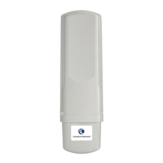
Introduces key features, uses, variants, and components of the 450 Platform Family.
Wireless Operation
Describes how the wireless link is operated, including modulation, power control, and security.
System Management
Introduces management system, web interface, configuration, security, alerts, and recovery.
Chapter 2: System Hardware
System Components
Describes system components of PTP and PMP, including accessories.
Cabling
Details about various cables used for installation and connections.
Lightning Protection Unit (LPU) and Grounding Kit
Describes lightning protection and grounding kits for installations.
Antennas and Antenna Cabling
Information on supported antennas and their necessary cabling.
GPS Synchronization
Details on Universal GPS (UGPS) and CMM for network synchronization.
Ordering the Components
Specifies Cambium part numbers for 450 Platform Family components.
Chapter 3: System Planning
Typical Deployment
Illustrates typical PMP/PTP 450 Platform site deployments with diagrams.
Site Planning
Factors for choosing sites, including grounding, lightning protection, and location.
Radio Frequency Planning
Planning links to conform to spectrum analysis and country regulations.
Link Planning
Factors for planning links, including range, obstacles, path loss, and throughput.
Planning for Connectorized Units
Considerations for planning connectorized ODUs with external antennas.
Data Network Planning
Factors for planning PMP/PTP 450 Platform data networks, including IP addressing.
Network Management Planning
Planning for remote management of links using SNMP.
Security Planning
Planning for links to operate in secure mode, including passwords and encryption.
Remote AP Deployment
Procedures and considerations for deploying Remote APs.
Chapter 4: Legal and Regulatory Information
Cambium Networks End User License Agreement
Defines terms, conditions, and grant of license for software and documentation.
Compliance with Safety Standards
Lists safety specifications and RF exposure limits for the 450 Platform Family.
Compliance with Radio Regulations
Describes compliance with radio regulations in various countries and type approvals.
Chapter 5: Preparing for Installation
Safety
Precautions and checks before proceeding with installation, including warnings.
Preparing for Installation
Pre-configuration procedures for units during staging before site installation.
Testing System Components
Procedures for unpacking, configuring, and testing system components.
Configuring Link for Test
Procedures for testing equipment's radio links and verifying proper registration.
Chapter 6: Installation
ODU Variants and Mounting Bracket Options
Details six different bracket options and their compatibility with ODU types.
Mount the ODU, LPU and Surge Suppressor
How to mount and ground integrated/connectorized ODUs and LPUs.
Installing the Copper Cat5e Ethernet Interface
Instructions for installing the copper Cat5e PoE interface from ODU to PSU.
Installing External Antennas to a Connectorized ODU
Procedures for mounting and connecting external antennas to connectorized ODUs.
Installing an Integrated ODU
Steps for mounting and connecting integrated ODUs.
Chapter 7: Configuration
Preparing for Configuration
Safety precautions and regulatory compliance checks before configuration.
Connecting to the Unit
Steps for connecting the management PC to the unit for configuration.
Using the Web Interface
Guide to logging into the web interface and navigating its options.
Quick Link Setup
Wizard for performing a quick link setup for the device.
Configuring IP and Ethernet Interfaces
Configuration of IP addressing, subnet masks, and gateway for network connectivity.
Upgrading the Software Version and Using CNUT
Instructions for checking software version and performing upgrades using CNUT.
General Configuration
Configuration settings for various Cambium product series.
Configuring Unit Settings Page
Settings for unit configuration, including time, date, and other parameters.
Configuring Synchronization
Settings for configuring synchronization parameters for network timing.
Configuring Security
Security settings for managing access, encrypting transmissions, and filtering.
Configuring Radio Parameters
Configuration of radio parameters for different product series and frequency bands.
Setting Up SNMP Agent
Steps to configure the SNMP agent for network management.
Configuring Syslog
Configuration of system logging for event recording and analysis.
Configuring Remote Access
Settings for enabling and managing remote access to the unit.
Monitoring the Link
Procedures for monitoring the status and performance of wireless links.
Configuring Quality of Service
Configuration of QoS parameters to manage network traffic priorities.
Chapter 8: Tools
Using Spectrum Analyzer Tool
How to use the Spectrum Analyzer tool for RF analysis.
Using the Alignment Tool
Procedure for using the Alignment Tool for aiming antennas.
Using the Link Capacity Test Tool
How to perform link capacity tests to evaluate performance.
Chapter 9: Operation
System Information
Viewing general status, session status, network interface, and layer 2 neighbors.
System Statistics
Viewing and interpreting various system statistics like scheduler, VLAN, and Ethernet.
Radio Recovery
Procedures for recovering radio configuration errors using console or default plug.
Chapter 10: Reference Information
Equipment Specifications
Detailed specifications for various PMP/PTP 450 Series hardware and software components.
Chapter 11: Troubleshooting
General Troubleshooting Procedure
General steps for troubleshooting, including fault isolation process and secondary steps.
Troubleshooting Procedures
Specific procedures for common issues like loss of connectivity or sync.
Power-Up Troubleshooting
Troubleshooting steps related to the power-up sequence of the device.
Registration and Connectivity Troubleshooting
Steps for resolving issues with SM/BHS registration and connectivity.
Logs
Information on accessing and interpreting logs for troubleshooting.
Table of Contents
Save PDF
Print
Rename the bookmark
Delete bookmark?
Delete from my manuals?
Login
Sign In
OR
Sign in with Facebook
Sign in with Google
Upload manual
Upload from disk
Upload from URL
Need help?
Do you have a question about the PMP 450i AP and is the answer not in the manual?
Questions and answers