Table of Contents
Advertisement
Quick Links
Cat. No. W516-E1-04
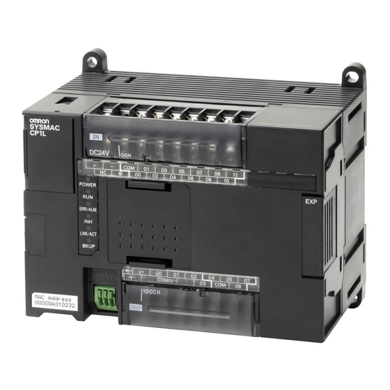
SYSMAC CP Series
CP1L-EL20D@-@
CP1L-EM30D@-@
CP1L-EM40D@-@
CP1L-EL/EM CPU Unit
Operation MANUAL
Advertisement
Table of Contents
Troubleshooting


Need help?
Do you have a question about the CP1L-EM30DT1-D and is the answer not in the manual?
Questions and answers