Table of Contents
Troubleshooting

Related Manuals for GE P54E


Summarization of Contents
Chapter 1 Introduction
Chapter Overview
Provides general information about the technical manual and an introduction to the devices described within it.
Foreword
Describes the manual's purpose, target audience, and typographical conventions used throughout.
Product Scope
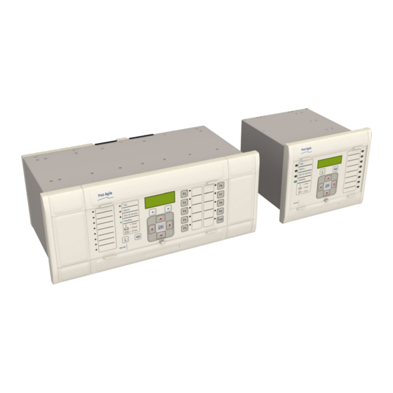
Details the capabilities and variants of the MiCOM P54A, P54B, P54C, and P54E IEDs.
Features and Functions
Outlines the protection functions, measurement functions, and control functions offered by the device.
Logic Diagrams
Explains the convention for elements used in logic diagrams and provides a key for understanding them.
Functional Overview
Presents a diagram illustrating the overall functional overview of the protection products in the P40L family.
Chapter 2 Safety Information
Chapter Overview
Provides information about safe handling of the equipment and emphasizes the need for familiarity with this chapter.
Health and Safety
Details personnel safety requirements and highlights the importance of qualified personnel working on electrical equipment.
Symbols
Illustrates and explains common symbols used throughout the manual and on the equipment.
Installation, Commissioning and Servicing
Covers hazards related to lifting and electrical safety, as well as specific requirements for UL/CSA/CUL and fusing.
Decommissioning and Disposal
Provides cautions regarding safe decommissioning and environmentally friendly disposal of the equipment.
Regulatory Compliance
Lists various compliance directives such as EMC, LVD, R&TTE, UL/CUL, and ATEX.
Chapter 3 Hardware Design
Chapter Overview
Provides information about the product's hardware design.
Hardware Architecture
Describes the main components and their interconnection, illustrating typical modules and data flow.
Mechanical Implementation
Details the modular hardware architecture, case variants, and lists the various boards used in the product.
Front Panel
Describes the components of the front panel, including LCD display, keypad, serial and parallel ports, and LEDs.
Rear Panel
Details the rear panel construction, slot allocations, and terminal block types.
Boards and Modules
Lists and describes the various PCBs and subassemblies that comprise the product's hardware.
Chapter 4 Software Design
Chapter Overview
Describes the software design of the IED, outlining the chapter's sections.
Sofware Design Overview
Conceptually categorizes the device software into system level, platform, and protection/control software.
System Level Software
Details the real-time operating system, system services software, and self-diagnostic software.
Platform Software
Describes the main functions of the platform software: record logging, settings database, and interfaces.
Protection and Control Functions
Explains the software processes for protection elements and measurement functions, including sample acquisition and frequency tracking.
Chapter 5 Configuration
Chapter Overview
Introduces the common methodology for setting parameters across the product series, including HMI and communications setup.
Settings Application Software
Explains the need for and use of the MiCOM S1 Agile software for configuring and managing IEDs.
Using the HMI Panel
Details how to navigate the HMI panel using the keypad and describes the functions of each key.
Line Parameters
Explains the required circuit information for line impedance, residual compensation, and phase rotation sequence.
Date and Time Configuration
Describes how to set the date and time, including options for SNTP, IRIG-B, and IEEE 1588 PTP signals.
Settings Group Selection
Explains how to select the setting group using opto inputs, menu selection, or hotkey menu.
Chapter 6 Current Differential Protection
Chapter Overview
Introduces the biased, phase-segregated, numerical Current Differential protection and its implementation.
Current Differential Protection Principle
Explains the principles of current differential protection based on Kirchhoff's Law and the Merz-Price principle.
Charging Current Compensation
Discusses the technical challenges of implementing multi-ended differential systems, focusing on capacitive current compensation.
Synchronisation of Current Signals
Explains the need for time alignment of current values from remote terminals for accurate differential calculations.
CT Saturation
Details the benefits of the GE patented technique for CT saturation and its enhanced fault discrimination.
CT Compensation
Explains how CT ratio compensation is used to scale current signals to match remote terminals.
Current Differential Intertripping
Describes the differential intertripping function and the permissive intertripping function.
Stub Bus Differential Protection
Explains how the product provides stub-bus protection associated with differential protection.
Application Notes
Provides practical application notes for multi-end current differential protection, feeder topology, and configuring the topology.
Chapter 7 Autoreclose
Chapter Overview
Provides a description of the Autoreclose (AR) functionality, including principles, logic diagrams, and applications.
Introduction to Autoreclose
Explains the concept of autoreclosing schemes and their benefits on circuits using time-graded protection.
Autoreclose Implementation
Defines terminology and describes the multiple-shot autoreclose function, including dead time and reclaim time.
Autoreclose System Map
Describes the system design of the Autoreclose logic, showing the interconnection of logic modules.
Logic Modules
Contains logic diagrams that help explain the Autoreclose function, including various inputs, outputs, and system maps.
Setting Guidelines
Provides guidance on setting de-ionising time, dead time, and reclaim time for autoreclose functions.
Chapter 8 CB Fail Protection
Chapter Overview
Describes the Circuit Breaker Fail Protection function, including principles, logic diagrams, and applications.
Circuit Breaker Fail Protection
Explains the importance of CBF protection for isolating faults and preventing system instability.
Circuit Breaker Fail Implementation
Details the implementation of CBF, including CB Fail Timers and Zero Crossing Detection.
Circuit Breaker Fail Logic
Provides logic diagrams for various parts of the circuit breaker fail function.
Application Notes
Discusses reset mechanisms for CB Fail timers and setting guidelines for CB Fail Timer and Undercurrent.
Chapter 9 Current Protection Functions
Chapter Overview
Introduces current protection functions used as backup, assuming familiarity with overcurrent protection principles.
Phase Fault Overcurrent Protection
Describes phase fault overcurrent protection as a form of back-up, detailing its implementation and directional element.
Negative Sequence Overcurrent Protection
Explains the use of NPSOC elements for detecting unbalanced faults and its implementation and directional element.
Earth Fault Protection
Details earth fault measurement methods, implementation, and the IDG curve.
Sensitive Earth Fault Protection
Describes SEF protection implementation, the EPATR B curve, and logic for sensitive earth fault protection.
High Impedance REF
Explains the High Impedance Restricted Earth Fault protection function and its principle.
Thermal Overload Protection
Describes thermal overload protection, including single and dual time constant characteristics.
Broken Conductor Protection
Explains the detection of broken conductors using negative phase sequence current and its implementation.
Chapter 10 Voltage Protection Functions
Chapter Overview
Provides an overview of the device's voltage protection functions, including principles, logic diagrams, and applications.
Undervoltage Protection
Discusses undervoltage conditions, their causes, and the implementation of undervoltage protection.
Overvoltage Protection
Explains overvoltage conditions, their causes, and the implementation of overvoltage protection.
Compensated Overvoltage
Describes the compensated overvoltage function and its calculation using line impedance and susceptance.
Residual Overvoltage Protection
Explains residual overvoltage protection, its implementation, and scenarios for VT failure.
Chapter 11 Frequency Protection Functions
Chapter Overview
Provides an overview of the device's frequency protection functions, including principles, logic diagrams, and applications.
Frequency Protection
Discusses the importance of balanced power generation and utilization for system frequency stability, covering underfrequency and overfrequency protection.
Independent R.O.C.O.F Protection
Explains the need for protection that responds to the rate of change of frequency, supplementing standard underfrequency protection.
Chapter 12 Monitoring and Control
Chapter Overview
Provides an overview of the product's monitoring and control functionality, covering various aspects.
Event Records
Explains how the IED records events in an event log and how to view and extract these records.
Disturbance Recorder
Describes the disturbance recorder feature, allowing recording of selected current and voltage inputs and digital signals.
Measurements
Details the system quantities measured and calculated by the device, which are updated every second.
CB Condition Monitoring
Explains how the device records various statistics related to circuit breaker trip operation for condition assessment.
CB State Monitoring
Describes how CB state monitoring is used to verify the open or closed state of a circuit breaker's auxiliary contacts.
Circuit Breaker Control
Details how circuit breaker control is possible using the CB Status Input cell and various control options.
Pole Dead Function
Explains the Pole Dead Logic used to determine and indicate that one or more phases of the line are not energized.
System Checks
Describes the System Checks function providing Live/Dead Voltage Monitoring, Check Synchronisation, and System Split indication.
Chapter 13 Supervision
Chapter Overview
Describes the supervision functions of the product, covering various aspects.
Current Differential Supervision
Discusses supervision of current differential protection, including starter supervision and communication path supervision.
Voltage Transformer Supervision
Explains the VTS function used to detect failure of AC voltage inputs, preventing maloperation of protection elements.
Current Transformer Supervision
Details the CTS function for detecting AC current input failures and its implementation methods.
Trip Circuit Supervision
Describes the TCS schemes for supervising the trip circuit, including the trip path and trip coil.
Chapter 14 Digital I/O and PSL Configuration
Chapter Overview
Introduces PSL Editor, configuration of digital inputs/outputs, and scheme logic concepts.
Configuring Digital Inputs and Outputs
Explains the flexible configuration of digital inputs and outputs using settings and programmable logic.
Scheme Logic
Describes the Scheme Logic as a functional module that handles mapping of inputs to outputs and interaction with the IED.
Configuring the Opto-Inputs
Details the configuration of optically isolated status inputs, including voltage ranges, filtering, and pick-up/drop-off.
Assigning the Output Relays
Explains how relay contact action is controlled using PSL and mapped DDB signals to drive output relays.
Fixed Function LEDs
Describes the four fixed-function LEDs on the front panel and their indicated conditions.
Configuring Programmable LEDs
Explains how programmable LEDs vary by model and how their illumination is controlled using a conditioner.
Function Keys
Describes the programmable function keys available for controlling functionality via PSL and their associated LEDs.
Control Inputs
Explains control inputs as software switches that can be set or reset locally or remotely to trigger PSL functions.
Chapter 15 Fibre Teleprotection
Chapter Overview
Provides information about the fibre-optic communication mechanism for unit schemes and teleprotection signalling.
Fibre Teleprotection Implementation
Details the Fibre Teleprotection interface as an integral part of Current Differential protection implementation.
Communications Supervision
Explains the supervision of communications to take appropriate action should they become degraded or lost.
IM64 Logic
Illustrates the IM64 channel fail and scheme fail logic, and general alarm signals logic.
Application Notes
Provides notes on scheme reconfiguration, alarm management, and alarm logic for fibre teleprotection.
Chapter 16 Electrical Teleprotection
Chapter Overview
Describes the operation of teleprotection functions, including principles, logic diagrams, and applications.
Introduction
Explains electrical teleprotection as an optional feature using communication links to create protection schemes.
Teleprotection Scheme Principles
Covers the three types of teleprotection commands: Direct Tripping, Permissive Tripping, and Blocking Scheme.
Implementation
Details the configuration of Electrical InterMiCOM using settings in the INTERMICOM COMMS and CONF columns.
Configuration
Explains how to customize individual command signals for teleprotection schemes based on security, speed, and dependability.
Connecting to Electrical InterMiCOM
Describes how to connect to Electrical InterMiCOM using EIA(RS)232 or fibre-optic connections.
Application Notes
Provides notes on electrical InterMiCOM settings, including baud rate, communications mode, and fallback modes.
Chapter 17 Communications
Chapter Overview
Provides information about substation automation, communications technologies, and IEDs.
Communication Interfaces
Summarizes the standard and optional communication interfaces, hardware, and protocols.
Serial Communication
Describes the physical layer standards used for serial communications: EIA(RS)485, K-Bus, and EIA(RS)232.
Standard Ethernet Communication
Details the Ethernet interface requirements for IEC 61850 or DNP3 over Ethernet, including fibre optic and copper connections.
Redundant Ethernet Communication
Explains redundancy requirements for critical applications and describes supported proprietary and standard protocols.
Simple Network Management Protocol (SNMP)
Describes SNMP as a network protocol designed to manage devices in an IP network.
Data Protocols
Lists the data protocols supported by the products, including Courier, MODBUS, IEC 60870-5-103, DNP3.0, and IEC 61850.
Read Only Mode
Explains the facility to enable or disable communication interfaces for security compliance.
Time Synchronisation
Describes mechanisms for synchronizing the IED's real-time clock, including IRIG-B, SNTP, and IEEE 1588 PTP.
Chapter 18 Cyber-Security
Overview
Discusses the need for cyber-security in substation environments due to advancements in technology and interconnected networks.
The Need for Cyber-Security
Explains cyber-security requirements like confidentiality, integrity, availability, and traceability.
Standards
Lists standards applicable to substation cyber-security, including NERC CIP, IEEE 1686, IEC 62351, and ISO/IEC 27002.
Cyber-Security Implementation
Describes the current implementation of cyber-security measures at the IED level and externally.
Chapter 19 Installation
Chapter Overview
Provides information about installing the product.
Handling the Goods
Discusses requirements for receiving, unpacking, and personal safety when handling the product.
Mounting the Device
Details the mounting procedures for the device, including flush panel mounting and rack mounting.
Cables and Connectors
Describes the types of wiring and connections to be used, including terminal blocks and cable specifications.
Case Dimensions
Provides case dimensions for 40TE, 60TE, and 80TE models, along with mounting and blanking plate information.
Chapter 20 Commissioning Instructions
Chapter Overview
Outlines the chapter's content, covering various commissioning tests and procedures.
General Guidelines
Provides general guidelines for commissioning IEDs, emphasizing self-checking devices and verifying hardware functionality.
Commissioning Test Menu
Describes the test facilities available under the COMMISSION TESTS menu, including opto-inputs, output relays, and DDB signals.
Commissioning Equipment
Lists recommended, essential, and advisory test equipment for commissioning the product.
Product Checks
Details product checks designed to ensure the device is undamaged, functioning correctly, and within tolerance.
Electrical InterMiCOM Communication Loopback
Explains how to configure a loopback for testing standard InterMiCOM communication (Electrical Teleprotection).
InterMiCOM 64 Communication
Describes the InterMiCOM 64 communication functionality and provides logic diagrams for channel fail and scheme fail.
Setting Checks
Ensures that all application-specific settings and programmable scheme logic settings have been correctly applied.
IEC 61850 Edition 2 Testing
Explains how to conduct online testing using IEC 61850 Edition 2 test modes, including IED test mode behavior.
Current Differential Protection
Details the current differential bias characteristic, including lower and upper slopes and operating time assignments.
Protection Timing Checks
Explains the need to check protection function timing, focusing on overcurrent checks and dependency conditions.
System Check and Check Synchronism
Describes the function for performing a comparison between line and bus voltages for autoreclose and manual closure.
Check Trip and Autoreclose Cycle
Explains how to test the trip and close operation automatically using application-specific settings.
End-to-End Communication Tests
Details the process of performing end-to-end testing of protection communications channels, removing loopbacks, and verifying connections.
Onload Checks
Provides warnings and guidelines for performing onload checks, including confirming voltage and current connections.
Final Checks
Outlines the final checks to be performed after commissioning, including restoring settings and checking records.
Chapter 21 Maintenance and Troubleshooting
Chapter Overview
Provides details on how to maintain and troubleshoot products based on Px4x and P40Agile platforms.
Maintenance
Details maintenance checks, including alarms, opto-isolators, output relays, and measurement accuracy.
Troubleshooting
Helps identify error conditions on the IED and suggests appropriate corrective actions or module replacements.
Chapter 22 Technical Specifications
Chapter Overview
Describes the technical specifications of the product, covering various functions and parameters.
Interfaces
Details the front serial port, download/monitor port, rear serial ports, and fibre rear serial port.
Protection Functions
Lists and describes various protection functions, including current differential, teleprotection, and overcurrent protections.
Monitoring, Control and Supervision
Covers voltage transformer supervision, current transformer supervision, differential current transformer supervision, and CB state monitoring.
Measurements and Recording
Details general measurement accuracy, disturbance records, and event, fault, and maintenance records.
Ratings
Specifies the ratings for AC measuring inputs, current transformers, voltage transformers, and auxiliary supply.
Input / Output Connections
Describes the isolated digital inputs, standard output contacts, high break output contacts, and watchdog contacts.
Mechanical Specifications
Details physical parameters, enclosure protection, mechanical robustness, and transit packaging performance.
Type Tests
Specifies requirements for insulation, creepage distances, clearances, and high voltage tests.
Environmental Conditions
Details operating, storage, and transit temperature ranges, ambient humidity, and corrosive environments.
Electromagnetic Compatibility
Outlines tests for immunity to high frequency disturbances, electrostatic discharge, fast transients, surges, radiated energy, and conducted disturbances.
Regulatory Compliance
Lists compliance with European Commission Directives (EMC, LVD, R&TTE), UL/CUL, and ATEX.
Need help?
Do you have a question about the P54E and is the answer not in the manual?
Questions and answers