Table of Contents
Advertisement
Quick Links
Advertisement
Table of Contents

Related Manuals for XTA DP424


Summarization of Contents
4 Series Quick Reference
Editing Channels
Adjusting channel gain and parameters using BACK/NEXT keys.
Accessing Menus
Navigating menu system using MENU, BACK, NEXT, and ENTER keys.
Menu Contents Overview
Listing of main sub-menus like Global Memory, Input Section, Crossover.
Operational Notes
Key points on crossover storage, meter display, and limiter attack/release.
Introduction to the 4 Series
Key Features
Highlights the DSP platform, flexible routing, and audio quality of the 4 Series.
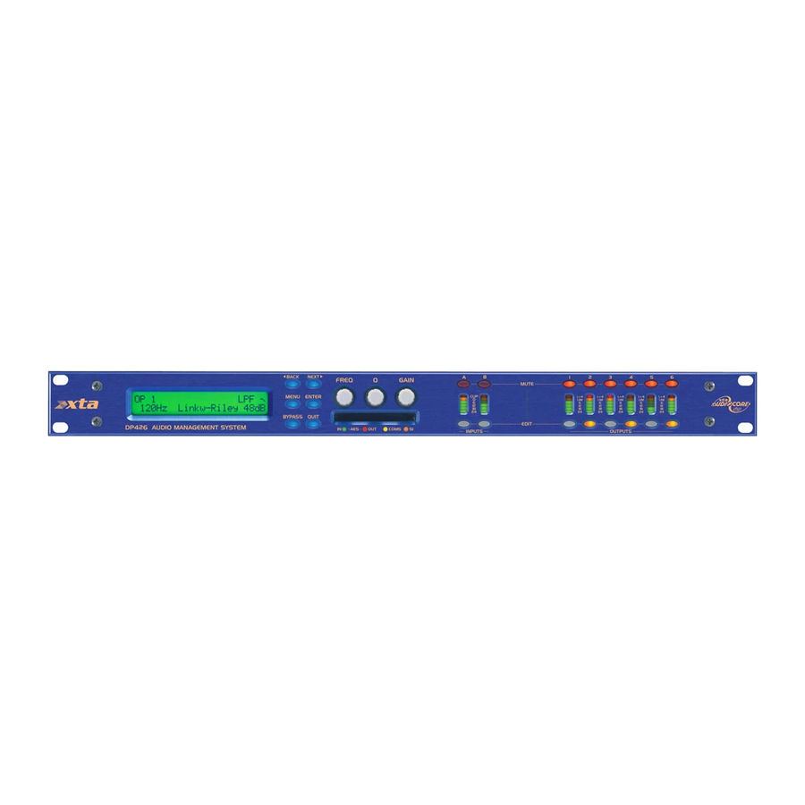
Front Panel Familiarisation
Display and Controls
LCD screen, control keys (MENU, BACK, NEXT, QUIT, ENTER) and rotary encoders.
Indicators and Slots
Status LEDs, PCMCIA/CF card slot for memory and updates.
Input and Output Sections
Controls and meters for signal paths, including MUTE and EDIT buttons.
Rear Panel Connections
Power and Interface Connectors
Mains inlet, RS232, RS485 ports for power and control.
Audio and AES I/O
XLR connectors for audio, AES digital inputs and outputs.
Operating the 4 Series
Start-up Procedure
Powering on the unit and initial display messages.
Preliminary Set-up
Initial steps for designing crossovers and configuring inputs/outputs.
Routing Options and Processing Blocks
Input Channel Processing
Details the processing blocks available on each input channel.
Output Channel Processing
Details the processing blocks available on each output channel.
Preset Routing Configurations
Predefined input-to-output routing examples for system setup.
Editing Input Channel Parameters
Input Gain Adjustment
Setting input signal level from -40dB to +6dB in 0.1dB steps.
Base Delay Configuration
Setting input delay up to 650mS with selectable units.
Input Graphic EQ
28-band graphic equalizer with adjustable Q behavior options.
Input Parametric EQ
Eight bands of parametric equalization with various filter shapes.
Editing Output Channel Parameters
Output Gain Adjustment
Setting output signal level from -40dB to +15dB in 0.1dB steps.
Output Polarity Switching
Inverting the phase of each output channel individually.
Output Delay Configuration
Setting output delay up to 650mS with selectable units.
Remote Control Interface Operation
RS232 Interface Details
Standard serial interface for PC connection, max 25ft range.
RS232 Single Unit Connection
Connecting one 4 Series unit to a PC via RS232 cable.
Shadow ID Numbers
RS485 Interface Functionality
Balanced system for data transmission up to 1km, supporting shadow IDs.
AES Inputs and Outputs
AES Input Selection
Digital audio input selection via rear panel switch with status LEDs.
AES Output Selection
Digital audio output configuration via the AES/EBU menu.
Security and Locking Features
Lock Type Options
Various lock types: User Specific, Xover, Changes, and Everything.
Entering the Password
Setting a four-digit code to activate selected security lock types.
Unlocking the Unit
Forgotten Password Procedure
Steps to unlock the unit using a break code if the password is lost.
PCMCIA Card and Compact Flash Card Usage
Preset Library Updates
Updating crossover library using a PCMCIA card with preset files.
Unit Software Updates
Updating unit software via a PCMCIA card containing new firmware.
Unit Cloning Functionality
Copying Software and Preset Files
Copying operating software or presets to a PCMCIA card.
Copying Data from Source Unit
Procedure to copy software/presets using specific security codes.
Loading Data into Destination Unit
Transferring software/presets to a running unit.
Cold Start Reboot Procedure
Rebooting and loading software after a remote download failure.
Advanced Audio Features
Graphic Equaliser Behaviour
Explains GQ600 and Special EQ response types.
The “GQ600” behaviour
EQ response with variable bandwidth based on cut/boost levels.
Program Limiter and “D-Max” Limiter
Program Limiter Details
Parameters for high-performance limiter: attack, release, and threshold.
Parametric Filter Types and Uses
Standard Parametric EQ
Basic parametric filter with adjustable frequency, Q, and Gain.
Appendix I – DP446 Default Crossover Configurations
2 x 3 Way Configuration
Default crossover setup for 2 inputs feeding 3 outputs each.
3 x 2 Way Configuration
Default crossover setup for 3 inputs feeding 2 outputs each.
Appendix II – DP444 Default Crossover Configurations
2 x 2 Way Configuration
Default crossover setup for 2 inputs feeding 2 outputs each.
1 x 4 Way Configuration
Default crossover setup for 1 input feeding 4 outputs.
Appendix III – DP424 Default Crossover Configurations
2 x 2 Way Configuration
Default crossover setup for 2 inputs feeding 2 outputs each.
1 x 4 Way Configuration
Default crossover setup for 1 input feeding 4 outputs.
Need help?
Do you have a question about the DP424 and is the answer not in the manual?
Questions and answers