Table of Contents
Advertisement
Advertisement
Table of Contents

Related Manuals for McAfee M-2950


Summarization of Contents
Preface
About this guide
Describes the guide's target audience, typographical conventions, and organization.
Find product documentation
Instructions on how to locate product documentation on the McAfee ServicePortal.
Introducing Network Security Sensors
About the M-2850/M-2950 Sensor
Describes the M-2850/M-2950 Sensor's network access control and IPS functionality.
M-2850/M-2950 Key Features
Lists the key hardware and performance features of the M-2850/M-2950 Sensor.
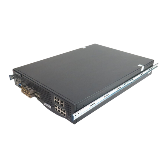
M-2850/M-2950 Physical Description
Details the physical attributes and ports of the M-2850/M-2950 Sensor.
Front and Back Panel LEDs
Explains the status indicators on the front and back panels of the Sensor.
Before you install
Usage restrictions
Outlines the limitations and prohibited uses for the Sensor appliance to maintain warranty and function.
Safety measures
Details critical safety warnings and precautions to prevent injury during installation and operation.
Working with fiber-optic ports
Explains the use of fiber-optic connectors and precautions for handling SFP ports.
Contents of the Sensor box
Lists the items included in the Sensor's shipping crate for installation.
Unpack the Sensor
Provides step-by-step instructions for safely unpacking the Sensor and its accessories.
Setting up the Sensor
Setup overview
Outlines the sequential steps involved in setting up the Sensor for initial configuration.
Position the Sensor
Advises on selecting a suitable, secure location for the Sensor, ideally within a communications rack.
Install the rails and ears on the chassis and rack
Describes how to attach rack-mounting rails and ears to the Sensor chassis for rack installation.
Mount the Sensor on a rack
Provides instructions for securely mounting the Sensor chassis into a standard equipment rack.
Remove a Sensor from the rack
Explains the procedure for safely detaching the Sensor chassis from a rack using release mechanisms.
Redundant power supply
Discusses the installation and function of a second, hot-swappable power supply for redundancy.
Install the power supply
Details the steps for inserting a power supply module into the Sensor chassis.
Remove the power supply
Provides instructions on how to safely remove a hot-swappable power supply module.
Cable the Sensor
Refers to the next section for instructions on connecting cables to Sensor ports.
Small form-factor pluggable modules
Introduces SFP modules used for connecting the Sensor to network interfaces.
SFP module
Describes the SFP module's specifications and function as a hot-swappable optical receiver.
Install a module
Provides step-by-step instructions for installing an SFP module into the Sensor.
Remove a module
Explains the procedure for safely removing an SFP module from the Sensor.
Power on the Sensor
Details the steps and prerequisites for powering on the Sensor.
Power off the Sensor
Recommends using CLI commands to safely shut down the Sensor before powering it off.
Attaching cables to the Sensor
Cable the Console port
Explains how to connect the console cable for initial setup and configuration of the Sensor.
Cable the Auxiliary port
Details how to connect a modem to the Auxiliary port for remote setup and configuration.
Cable the fail-open port
Mentions fail-open functionality and the need for a bypass kit for monitoring ports.
Cable the Management port
Provides instructions for connecting an Ethernet cable to the Management port for network communication.
Cable the Monitoring ports
Explains how to connect cables to the Sensor's monitoring ports for network traffic analysis.
How to use peer ports
Explains the pairing of monitoring ports (e.g., 1A/1B) required for full-duplex Sensor deployments.
Default Monitoring port speed settings
Specifies the default speed and duplex settings for monitoring ports, including auto-negotiation.
Cable types for routers, switches, hubs, and PCs
Describes the types of cables needed to connect the Sensor to various network devices.
Cable for in-line
Details how to connect the Sensor's Gigabit Ethernet ports for fail-close in-line monitoring.
Connect the cables for tap mode
Provides instructions for connecting the Sensor to a third-party external tap for tap mode deployment.
Connect the cables for SPAN or hub mode
Explains how to connect the Sensor to SPAN ports or hubs for monitoring.
Cable the fail-over interconnection
Guides on connecting two Sensors for fail-over communication using specific ports and cables.
About the Fail-Open Hardware
Discusses the fail-open hardware kit and its role in preventing network downtime during Sensor failure.
Fail-Open Bypass Switch Functionality
Explains how the bypass switch functions to maintain traffic flow during Sensor failure or recovery.
Troubleshooting the Sensor
Troubleshooting the Sensor
Lists common problems, their possible causes, and recommended solutions for the Sensor.
Technical Specifications
Sensor Specifics
Details physical dimensions, weight, voltage, frequency, vibration, and power requirements.
Ambient Temperature Range (Non-condensing)
Specifies the operating and non-operating temperature ranges for the Sensor.
Relative Humidity (Non-condensing)
Lists the acceptable operating and non-operating relative humidity levels for the Sensor.
System Heat Dissipation
Provides information on heat dissipation, airflow, and altitude limits for the Sensor.
Regulatory, Compliance, and Safety Information
Sensor Regulatory, Safety, and Compliance
Details compliance with CE directives and lists specific safety and EMC standards met by the Sensor.
Electromagnetic Compliance (Emissions)
Lists standards related to electromagnetic emissions, such as FCC, VCCI, and AS/NZS compliance.
Need help?
Do you have a question about the M-2950 and is the answer not in the manual?
Questions and answers