
Related Manuals for Reflex iC60H

Summarization of Contents
Safety Information
Important Information
General important information and safety messages for device operation.
NOTICE
Addresses practices not related to physical injury.
PLEASE NOTE
Guidance on proper installation and operation by qualified personnel.
About the Book
Document Scope
Specifies the intended audience and purpose of the manual.
Validity Note
Clarifies the intended use of Reflex iC60 circuit breakers.
Related Documents
Lists other relevant technical publications for the product.
User Comments
Provides contact information for document feedback and suggestions.
Introduction
Overview
Provides a general overview of the Reflex iC60 integrated control circuit breaker.
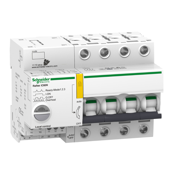
Description
Details the Reflex iC60 circuit breaker components and interfaces.
Installation
Assembly
Instructions for assembling the Reflex iC60 circuit breaker with auxiliaries.
Connection
Details on connecting the Reflex iC60 circuit breaker terminals.
Safety Instructions
Crucial safety warnings for electrical shock, explosion, or arc flash during installation.
Connection Blocks
Diagrams and descriptions of connection blocks for the Reflex iC60 with Ti24 interface.
Description of the Terminals
Detailed explanation of terminals for power supply, control inputs, and indication outputs.
E interface I/O terminal block Ti24
Description of the Ti24 interface terminal block functions and connections.
Connection Characteristics
Specifications for terminal blocks, tightening torque, wire size, and cable types.
Connection Diagrams
Diagrams illustrating various connection configurations for the circuit breaker.
Supplying the Control Inputs Using an iMDU Auxiliary
Explains how to supply control inputs using an iMDU auxiliary for 24/48 V AC/DC.
Use
Operating Modes
Details the different operating modes available for the Reflex iC60 circuit breaker.
Reflex iC60 Integrated Control Circuit Breaker Functions
Table outlining functions for each operating mode based on circuit breaker type.
Mode 1 Operation
Explains Mode 1 operation for Reflex iC60 without and with Ti24 interface.
Mode 2 Operation
Details Mode 2 operation for Reflex iC60 without and with Ti24 interface.
Mode 3 Operation
Describes Mode 3 operation and its control inputs for Reflex iC60 with Ti24.
Connection diagram 1
Illustrates connection diagram 1 for Mode 3 using a selector for control.
Connection diagram 2
Illustrates connection diagram 2 for Mode 3, considering controls on Y2 and Y3.
Checking the Operating Mode
How to check the current operating mode using the LED indicator.
Default setting
Lists the default operating modes for different Reflex iC60 circuit breaker types.
Selection of the Operating Mode
Step-by-step procedure for selecting and confirming the circuit breaker's operating mode.
Operating Mode Selection Steps
Detailed steps for selecting and confirming the circuit breaker operating mode.
Automatic Overheat Protection
Explanation of the automatic overheat protection feature and its activation.
Overheat Protection Description
Explains how overheat protection is activated and its effects on remote control.
Overheat Protection Operating Principle
Describes how overheat protection is estimated based on control order frequency and cooling time.
Overheat Protection Activation
Discusses when overheat protection is likely to be activated during operation.
Correct Use of Overheat Protection
Provides guidance on using the circuit breaker to avoid frequent overheat protection activation.
Operation
Describes the local and remote indication of circuit breaker status.
Local Indication (LED)
Explains the meaning of LED indicator states for circuit breaker status.
Remote Indication
Details the states of output indications for circuit breaker status, with and without Ti24.
Padlocking
Procedure for padlocking the circuit breaker to ensure electrical isolation during work.
Application examples
Outdoor parking lot lighting
Example of controlling outdoor parking lot lighting with Reflex iC60 circuit breakers.
Office lighting
Example of controlling office lighting with automatic switch-off using Reflex iC60.
Workshop lighting
Example of controlling workshop lighting with Reflex iC60, using PLC and local modes.
Technical Characteristics
General characteristics
Presents general technical specifications such as degree of protection, weight, and environmental resistance.
Control Circuit: Inputs Y1 and Y2
Specifies control voltage, pulse duration, response time, and consumption for inputs Y1 and Y2.
Remote Indication: O/C, auto/OFF
Details the capacity of volt-free changeover contacts for O/C and auto/OFF indications.
Ti24 Interface Specifications
Lists consumption and capacity for the Ti24 interface inputs and outputs.
Dimensions
Provides dimensions of the Reflex iC60 circuit breaker and Vigi iC60 auxiliaries.
Need help?
Do you have a question about the iC60H and is the answer not in the manual?
Questions and answers