Table of Contents
Advertisement
and field service checklist
Table of ConTenTs
Page 1
System Components
Page 2 & 3
Page 4
Page 5
Page 6
Preliminary Circuit Analysis
Page 7
Page 8
SyStem ComponentS
Amplifiers
A1044U
Discharge Temperature Sensors: use with Mixing Tube
Mixing Tubes: used with sensors
© 2008 Maxitrol Company, All Rights Reserved
Series 44 Installation Instructions
A1044U (replaces all A1044L1, suitable re-
placement for A1044 [C,D,E,H]) (includes 0,
10, or 20 second low fire start capability.)
A1044UF (replacement for A1044FL1)
A1044UG (replacement for A1044G[L1])
A1044 (min. 40° to 80° F/ max. 80° to 140° F)
A1044C (min. 20° to 60° F/ max. 80° to 140° F)
A1044D (min. 20° to 60° F/ max. 35° to 75° F)
A1044E (min. 20° to 60° F/ max. 60° to 120° F)
A1044G (min. 40º to 80º F / max. 160º to 210º F)
A1044H (min. 40º to 80º F / max. 100º to 160º F)
note: Amplifier and Discharge Tempera-
ture Sensor must have same temperature
range to be compatible.
Sensors compatible with A1044U:
TS144 (min. 40° to 80° F/max. 80° to 140° F)
TS144C (min. 20° to 60° F/max. 80° to 140° F)
TS144D (min. 20° to 60° F/max. 35° to 75° F)
TS144E (min. 20° to 60° F/max. 60° to 120° F)
TS144H (min. 40º to 80º F / max. 100º to 160º F)
Sensors compatible with A1044UF:
TS144F (min. 40º to 80º F / max. 60º to 95º F)
Sensors compatible with A1044UG:
TS144G (min. 40º to 80º F / max. 160º to 210º F)
MT1-9 or MT2-9 (9" length)
MT1-12 or MT2-12 (12" length)
MT1-23 or MT2-23 (23" length)
MT1-28 or MT2-28 (28" length)
MT1-57 (57" length)
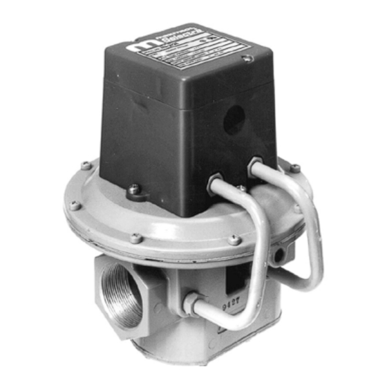
Valves
Selectrastat (Senses and Selects)
Space temperature Selector
Space temperature Sensor
1
M411 (3/8" & 1/2" pipe size)
M511 (1/2" & 3/4" pipe size)
M611 (3/4" & 1" pipe size)
MR212D (1", 1¼", 1½ pipe size)
MR212E (1½" & 2" pipe size)
MR212G (2½" & 3" pipe size)
MR212J (4" flanged)
MR212D-2, E-2, G-2 & J-2 (same pipe
sizes as MR212D-J except used for 2-
speed blower or dual fuel operation)
note: M (Modulator) valve requires an
upstream pressure regulator for low fire &
high fire settings. MR (Modulator/Regula-
tor) valve requires no upstream pressure
regulator up to 5 psi inlet.
T244 (55° to 90° F)
T244A (40° to 80° F)
or optional pair to replace
Selectrastat
TD244 (wall mount 55° to 90° F)
TD244A (wall mount 40° to 80° F)
TD244P (panel mount 55° to 90° F)
TD244AP (panel mount 40° to 80° F)
TS244 (55° to 90° F)
TS244A (40° to 80° F)
note: Space Temperature
Selector and Space Tem-
perature Sensor must have
same temperature range to be
compatible.
Advertisement
Table of Contents

Related Manuals for Maxitrol 44 series


Summarization of Contents
System Components
Amplifiers
Details different amplifier models and their compatibility with sensors.
Valves
Lists various Maxitrol Modulator and Modulator-Regulator valves.
Selectrastat (Senses and Selects)
Describes the component that senses and selects space temperature.
Space Temperature Selector
Component for selecting desired space temperature range.
Space Temperature Sensor
Component that senses space temperature.
Discharge Temperature Sensors
Sensors used with mixing tubes for discharge air control.
Mixing Tubes
Components used with sensors for discharge air temperature sensing.
Installation of Components
Wiring Run
Guidelines for routing control wires to prevent interference.
Amplifier Installation
Recommendations for amplifier placement to protect from environment.
Selectrastat Mounting
Instructions for mounting Selectrastat to sense space temperature.
Remote Temperature Selector
Mounting instructions for optional remote temperature selector.
Remote Temperature Sensor
Mounting instructions for optional remote temperature sensor.
Typical Gas Trains
Modulator or Modulator-Regulator Valve Mounting
Mounting guidelines for modulator/regulator valves in gas piping.
Preliminary Circuit Analysis
Section I: Initial Voltage Checks
Steps to check voltage at amplifier terminals for basic circuit function.
Section II: Power Off Testing
Procedure for checking amplifier with power off and then on.
Section III: Burner Flame Observation
Observing burner response during test potentiometer adjustment.
Section IV: Temperature Sensing Circuitry
Testing discharge air temperature sensing and control.
Section V: Reconnecting Components
Final step to remove test equipment and reconnect.
Temperature Calibration
Minimum Discharge Air Temperature Calibration
Procedure to calibrate minimum discharge air temperature setting.
Maximum Discharge Air Temperature Calibration
Procedure to calibrate maximum discharge air temperature setting.
Space Temperature Calibration
Procedure to calibrate space temperature sensing and control.
Valve Adjustments
MR 212 Valve Adjustments
High fire and low fire adjustments for the MR 212 valve.
M411, 511, 611 Valve Adjustments
High fire and low fire adjustments for M411, 511, 611 valves.
Need help?
Do you have a question about the 44 series and is the answer not in the manual?
Questions and answers