Table of Contents
Advertisement
and field service checklist
Table of ConTenTs
Page 1
System Components
Page 2 & 3
Page 4
Page 5
Page 6
Preliminary Circuit Analysis
Page 7
Page 8
SyStem ComponentS
Amplifiers
A1044U
Discharge Temperature Sensors: use with Mixing Tube
Mixing Tubes: used with sensors
© 2008 Maxitrol Company, All Rights Reserved
Series 44 Installation Instructions
A1044U (replaces all A1044L1, suitable re-
placement for A1044 [C,D,E,H]) (includes 0,
10, or 20 second low fire start capability.)
A1044UF (replacement for A1044FL1)
A1044UG (replacement for A1044G[L1])
A1044 (min. 40° to 80° F/ max. 80° to 140° F)
A1044C (min. 20° to 60° F/ max. 80° to 140° F)
A1044D (min. 20° to 60° F/ max. 35° to 75° F)
A1044E (min. 20° to 60° F/ max. 60° to 120° F)
A1044G (min. 40º to 80º F / max. 160º to 210º F)
A1044H (min. 40º to 80º F / max. 100º to 160º F)
note: Amplifier and Discharge Tempera-
ture Sensor must have same temperature
range to be compatible.
Sensors compatible with A1044U:
TS144 (min. 40° to 80° F/max. 80° to 140° F)
TS144C (min. 20° to 60° F/max. 80° to 140° F)
TS144D (min. 20° to 60° F/max. 35° to 75° F)
TS144E (min. 20° to 60° F/max. 60° to 120° F)
TS144H (min. 40º to 80º F / max. 100º to 160º F)
Sensors compatible with A1044UF:
TS144F (min. 40º to 80º F / max. 60º to 95º F)
Sensors compatible with A1044UG:
TS144G (min. 40º to 80º F / max. 160º to 210º F)
MT1-9 or MT2-9 (9" length)
MT1-12 or MT2-12 (12" length)
MT1-23 or MT2-23 (23" length)
MT1-28 or MT2-28 (28" length)
MT1-57 (57" length)
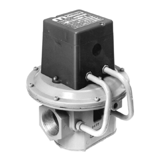
Valves
Selectrastat (Senses and Selects)
Space temperature Selector
Space temperature Sensor
1
M411 (3/8" & 1/2" pipe size)
M511 (1/2" & 3/4" pipe size)
M611 (3/4" & 1" pipe size)
MR212D (1", 1¼", 1½ pipe size)
MR212E (1½" & 2" pipe size)
MR212G (2½" & 3" pipe size)
MR212J (4" flanged)
MR212D-2, E-2, G-2 & J-2 (same pipe
sizes as MR212D-J except used for 2-
speed blower or dual fuel operation)
note: M (Modulator) valve requires an
upstream pressure regulator for low fire &
high fire settings. MR (Modulator/Regula-
tor) valve requires no upstream pressure
regulator up to 5 psi inlet.
T244 (55° to 90° F)
T244A (40° to 80° F)
or optional pair to replace
Selectrastat
TD244 (wall mount 55° to 90° F)
TD244A (wall mount 40° to 80° F)
TD244P (panel mount 55° to 90° F)
TD244AP (panel mount 40° to 80° F)
TS244 (55° to 90° F)
TS244A (40° to 80° F)
note: Space Temperature
Selector and Space Tem-
perature Sensor must have
same temperature range to be
compatible.
Advertisement
Table of Contents


Need help?
Do you have a question about the Selectra and is the answer not in the manual?
Questions and answers