
Related Manuals for Honeywell Bendix


Summarization of Contents
Section I General Information
1.1 Introduction
Provides an overview of the manual's content concerning the Bendix/King KI 208 and KI 209.
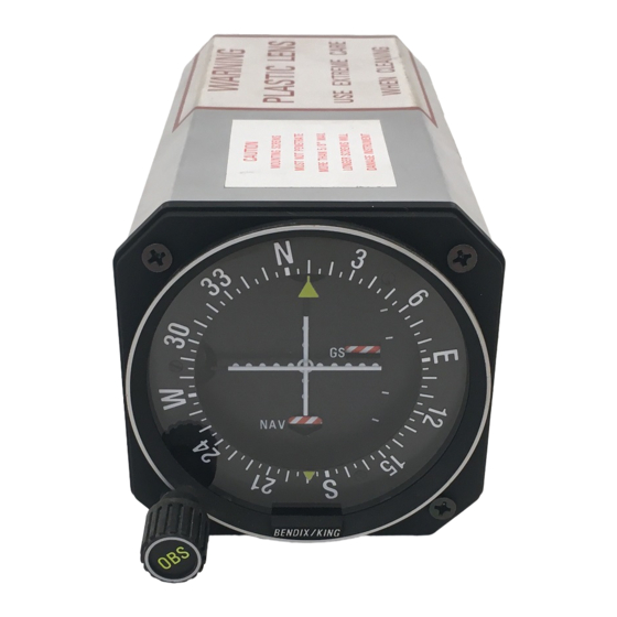
1.2 Equipment Description
Details the functions and capabilities of the KI 208 VOR Indicator and KI 209 ILS Indicator.
1.3 Technical Characteristics
Outlines the specifications, compliance, size, weight, and power requirements of the KI 208 and KI 209.
1.4 Units and Accessories Supplied
Lists the specific part numbers for the KI 208, KI 209, and associated installation kits.
1.5 Accessories Required, But Not Supplied
Lists essential accessories and tools needed for installation but not included with the unit.
1.6 License Requirements
States that there are no specific license requirements for this equipment.
1.7 Requirements for TSO'd VOR/ILS/Glideslope System
Specifies requirements for navigation receivers to form a completely TSO'd system with the KI 208/209.
Section II Installation
2.1 General
Provides suggestions and factors to consider before installing the KI 208/209 Indicator.
2.2 Unpacking and Inspecting Equipment
Details the procedure for carefully unpacking and inspecting the unit for shipping damage.
2.3 Installation KI 208, KI 209
Covers the installation procedure, including panel location, mounting, and cabling.
2.4 Post Installation Checkout
Describes recommended operational ramp tests and flight tests to ensure satisfactory performance after installation.
Section III Operation
3.1 Equipment Operation
Explains how to operate the KI 208, KI 209 units using their front panel controls and related transceivers.
3.1.1 VOR Operation (KI 208, KI 209)
Describes VOR frequency selection, station identification, and interpretation of VOR indications for navigation.
3.1.2 Localizer Operation (KI 208, KI 209)
Details how to identify localizer stations and maneuver the aircraft for on-course approach using the deviation needle.
3.1.3 Glideslope Operation (KI 209)
Explains how the glideslope needle provides vertical steering information during ILS approaches and how to interpret its indications.
3.2 Indicator Control Functions KI 208, KI 209
Introduces the control functions of the KI 208 and KI 209, referencing figures for visual details.
Need help?
Do you have a question about the Bendix and is the answer not in the manual?
Questions and answers