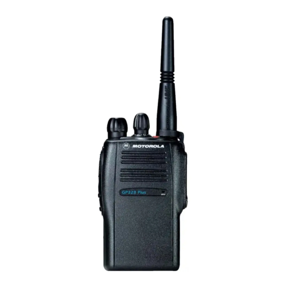
Summarization of Contents
Safety Information
Product Safety and RF Energy Exposure
Provides general safety information and details RF energy exposure for portable two-way radios.
RF Energy Exposure Awareness and Control
Information on RF energy exposure, control, and operational instructions for occupational use.
Operational Warnings
Potentially Explosive Atmospheres
Instructions for operating radios in potentially explosive environments, including fueling areas.
Blasting Caps and Blasting Areas
Warning to turn off radios near electrical blasting caps or in posted blasting areas.
Section 1 Introduction
Scope of Manual
Specifies the intended audience and scope of the service manual.
Warranty and Service Support
Details Motorola's long-term support, including product exchange, repair, and spare parts.
Section 2 Service Aids
Recommended Test Tools
Lists recommended test tools and their applications for working on the radio family.
Section 3 Power Up Self-Test
Error Codes
Lists error codes generated during the power-up self-test and their corrective actions.
Section 4 Controller Information
Radio Power Distribution
Illustrates the DC distribution throughout the radio board, detailing power flow and component supply.
Controller Schematics
Provides the complete controller schematic diagram, showing interconnections between major ICs and components.
Section 5A Model Chart and Test Specifications (136-174 MHz)
Model Chart
Lists various GP Series models, their descriptions, and associated items like antennas and user guides.
Specifications (for GP328 Plus)
Details general, transmitter, and receiver specifications for the GP328 Plus radio model.
Receiver
Details receiver specifications, including front-end, back-end, and AGC circuit functions.
Troubleshooting Charts
Provides detailed troubleshooting flow charts for controller, receiver, transmitter, synthesizer, and VCO.
Section 5B Model Chart and Test Specifications (403-470 MHz)
Model Chart
Lists various GP Series UHF Band 1 models and their descriptions, including antennas.
Specifications (for GP328 Plus)
Details general, transmitter, and receiver specifications for the GP328 Plus UHF radio.
Receiver
Details UHF receiver specifications, including front-end, back-end, and AGC circuit functions.
Troubleshooting Charts
Provides troubleshooting flow charts for controller, receiver, transmitter, synthesizer, and VCO.
Section 5C Model Chart and Test Specifications (450-527 MHz)
Model Chart
Lists various GP Series UHF Band 2 models, their descriptions, and associated items.
Specifications (for GP328 Plus)
Details general, transmitter, and receiver specifications for the GP328 Plus UHF radio.
Receiver
Details UHF receiver specifications, including front-end, back-end, and AGC circuit functions.
Troubleshooting Charts
Provides troubleshooting flow charts for controller, receiver, transmitter, synthesizer, and VCO.
Section 5D Model Chart and Test Specifications (330-400 MHz)
Model Chart
Lists GP Series models for the 330-400 MHz band, their descriptions, and associated items.
Specifications (for GP328 Plus)
Details general, transmitter, and receiver specifications for the GP328 Plus 330-400 MHz radio.
Receiver
Details receiver specifications, including front-end, back-end, and AGC circuit functions.
Troubleshooting Charts
Provides troubleshooting flow charts for controller, receiver, transmitter, synthesizer, and VCO.
Section 6 Flex Layout/Schematic Diagrams and Parts Lists
RF-Controller Interconnect Flex
Illustrates the flex layout for RF-Controller interconnect, Rev A and Rev B.


Need help?
Do you have a question about the GP338 XLS and is the answer not in the manual?
Questions and answers