Table of Contents
Advertisement
Quick Links
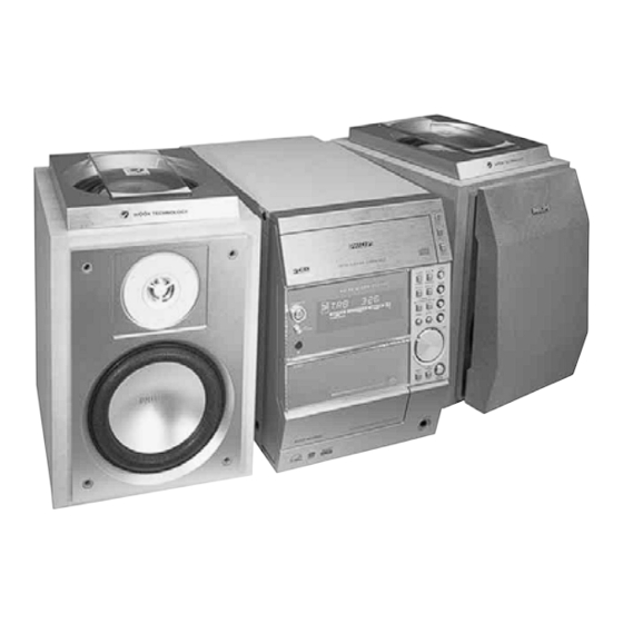
Micro System
Service
Service
Service
Service Manual
©
Copyright 2001 Philips Consumer Electronics B.V. Eindhoven, The Netherlands
All rights reserved. No part of this publication may be reproduced, stored in a retrieval system or
transmitted, in any form or by any means, electronic, mechanical, photocopying, or otherwise
without the prior permission of Philips.
Published by KC 0110 Service Audio
TABLE OF CONTENTS
Location Of Pc Boards & Version variations ................ 1-2
Technical Specifications ............................................. 1-3
Measurement Setup .................................................... 1-4
Service Aids, Safety Instruction, etc. .......................... 1-5
Instruction for use: European version excerpt .......... 2-1
Additional features .................. 2-13
Disassembly Instructions & Service positions ........... 3-1
Service Test Programs ............................................... 3-4
Set Block Diagram ......................................................... 4
Set Wiring Diagram ........................................................ 5
Front Display Board ....................................................... 6
Eco6 Tuner Board: System Non-Cenelec ................ 7A
System Cenelec ........................ 7B
Front Control Board ....................................................... 8
Etf6-Le Tape Module ................................................... 9
3TDC Module ............................................................... 10
Power 2001 Module ..................................................... 11
Set Mechanical Exploded view & parts list ................. 12
Printed in The Netherlands
Subject to modification
MC-70/
Page
Class 1
GB
21/21M/22/37
COMPACT
DIGITAL AUDIO
3139 785 22720
Advertisement
Table of Contents

Related Manuals for Philips MC-22


Summarization of Contents
LOCATION OF PC BOARDS
VERSION VARIATIONS
Lists features and board variations across different models.
SPECIFICATIONS
GENERAL
General system specifications like voltage, frequency, power consumption, dimensions.
AMPLIFIER
Amplifier output power, frequency response, controls, and output specifications.
COMPACT DISC
CD playback specifications including frequency response, S/N ratio, distortion, and channel separation.
MEASUREMENT SETUP
Tuner FM & AM
Setup diagrams for FM and AM tuner measurements.
CD & Recorder
Setup diagrams for CD player and cassette recorder measurements.
SERVICE AIDS
Service Tools & ESD Equipment
Specialized tools and ESD protection equipment for servicing.
Cassette & Disc Aids
Test cassettes and discs for tape and CD servicing.
HANDLING CHIP COMPONENTS
DISMOUNTING & MOUNTING
Procedures for removing and installing chip components.
PRECAUTIONS & EXAMPLES
Precautions and examples for safe component handling.
ESD SAFETY PRECAUTIONS
General ESD & Repair Warnings
Warnings about ESD risks and repair regulations.
Laser Safety & Leakage Current Tests
Warnings about laser safety and post-service tests.
GENERAL INFORMATION & PREPARATIONS
Environmental, Safety & Accessories
Information on disposal, safety, and included accessories.
Rear Connections & Power Setup
Instructions for connecting rear components and power.
PREPARATIONS (Continued)
Speaker & Optional Connections
Connecting speakers and optional external equipment.
Battery Insertion & Digital Output
Inserting remote batteries and digital audio output connection.
CONTROLS
System & Remote Controls
Identification and function of system and remote controls.
BASIC FUNCTIONS
Plug and Play Installation
Automatic RDS station storage and installation procedure.
BASIC FUNCTIONS (Continued)
Demonstration Mode & Power States
Managing demo mode and system power states.
Dimming & Volume Control
Adjusting display brightness and sound volume.
BASIC FUNCTIONS (Continued)
Bass/Treble & Surround Sound
Adjusting bass, treble, and surround sound effects.
CD OPERATION
Disc Playback & Loading
How to load discs and initiate playback.
CD OPERATION (Continued)
Playback Controls & Searching
Managing playback, stopping, resuming, and searching tracks.
Track Programming & Repeat Modes
Programming tracks and setting repeat playback options.
RADIO RECEPTION
Preset Station Management
Storing, selecting, and erasing preset radio stations.
RDS Features & Time Setting
Utilizing RDS data and setting the clock via RDS time.
RADIO RECEPTION (Continued)
NEWS Function & Tuner Mode
Activating and managing the NEWS function.
TAPE OPERATION/RECORDING
Tape Playback Modes & Controls
Instructions for tape playback, stopping, and changing sides/modes.
TAPE OPERATION/RECORDING (Continued)
Recording Preparation & One Touch
Preparing for recording and using one-touch recording.
CD Synchro Recording
How to record CDs synchronized with CD playback.
CLOCK/TIMER
Clock Setting & Display
Setting the clock and managing its display mode.
Timer Setting & Management
Setting, activating, deactivating, and checking the timer.
MAINTENANCE
Cleaning Procedures
Instructions for cleaning the cabinet, discs, and lens.
TROUBLESHOOTING
Common CD, General, Radio & Tape Issues
Addressing issues with CD, general, radio, and tape functions.
CONTROLS
Tape, Timer, Repeat, Shuffle & Resume
Functions of tape, timer, repeat, shuffle, and resume controls.
Radio Reception
Tuning Grid Adjustment
How to change tuning grid frequency steps for specific versions.
RADIO RECEPTION (Continued)
Preset Station Management
Storing, selecting, and erasing preset radio stations.
RDS Features & Time Setting
Utilizing RDS data and setting the clock via RDS time.
DISMANTLING INSTRUCTIONS
Cassette Cover & 3DTC Module Removal
Steps for removing the cassette cover and 3DTC/tuner board.
Front Panel Assembly Detachment
How to detach the front panel assembly from the main unit.
DISMANTLING INSTRUCTIONS (Continued)
Front Panel & Rear Panel Dismantling
Procedures for dismantling the front and rear panels.
Bottom Assembly Dismantling
Steps for dismantling the bottom assembly components.
SERVICE POSITIONS & REPAIR HINTS
Service Positions A & B
Illustrations of service positions A and B.
Service Positions C & D
Illustrations of service positions C and D, noting flex wire usage.
SERVICE TEST PROGRAM
TUNER & TEST Procedures
Tuner tests and various system tests.
Error Codes & Tables
Table of error codes and associated descriptions.
SET BLOCK DIAGRAM
Signal Paths & Main Processors
Block diagrams of signal paths and main processors.
Control & Power Circuits
Block diagrams of control, power, and RDS circuits.
SET WIRING DIAGRAM
ETF 6 & CD Wiring
Wiring diagrams for ETF 6 tape deck and CD components.
Display, Combi & Micro/3DTC Wiring
Wiring for front display, Combi, Micro, and 3 DTC modules.
FRONT DISPLAY BOARD
FTD Display Pins & Circuit Diagram
Pin assignment and circuit diagram for the FTD display.
Component & Parts List
Component layout and electrical parts list for the display board.
CIRCUIT DIAGRAM
Component List References
References to component lists within the circuit diagram.
COMPONENT LAYOUT
Component Placement Diagram
Layout of components on the board.
CHIP LAYOUT
Chip Placement Diagram
Layout of chips on the board.
ELECTRICAL PARTS LIST - FRONT DISPLAY BOARD
MISCELLANEOUS & CAPACITORS
List of miscellaneous parts and capacitors.
RESISTORS
List of resistors with values and tolerances.
ELECTRICAL PARTS LIST - FRONT DISPLAY BOARD (Continued)
Resistors, Coils & Filters
List of resistors, coils, and filters with specifications.
Diodes, Transistors & ICs
List of diodes, transistors, and integrated circuits.
ECO6 Tuner Board
Blockdiagram, Schematic
Block and schematic diagrams of the ECO6 Tuner Board.
Component Layout & Parts List
Component layout and electrical parts list for the ECO6 Tuner Board.
TUNER BOARD ECO6 / SYSTEMS NON CENELEC
Aerial, RF & Oscillator Circuits
Connections and circuits for aerials, RF, and oscillators.
IF Stages, Stereo Decoder & RDS
FM IF stages, stereo decoder, and RDS circuitry.
TUNER ADJUSTMENT TABLE (ECO6 Cenelec FM/MW - and FM/MW/LW - versions with AM-frame aerial)
FM, MW & LW Tuning Adjustments
Adjustment tables for FM, MW, and LW tuning.
IF, VCO & AM AFC Adjustments
Adjustment procedures for IF stages, VCO, and AM AFC.
Electrical Partslist ECO6 SYSTEMS NON-CENELEC
MISCELLANEOUS & CAPACITORS
List of miscellaneous parts and capacitors.
Resistors, Coils, Diodes, Transistors & ICs
List of resistors, coils, diodes, transistors, and integrated circuits.
FRONT CONTROL BOARD
Standby (Power) & Key Control Parts
Circuit and layout for standby power and key controls.
Headphone, Jog, CDC Key & Parts List
Circuits, layouts, and parts for headphone, jog, CDC key functions.
KEY CONTROL (KEYB. 1) PART - CIRCUIT & LAYOUT DIAGRAMS
Component Placement
Component placement for key controls.
LIGHTWASH PART - CIRCUIT & LAYOUT DIAGRAMS
Component Placement
Component placement for lightwash function.
HEADPHONE PART - CIRCUIT & LAYOUT DIAGRAMS
Component Placement
Component placement for the headphone jack.
JOG/VOLUME & CDC KEY CONTROLS
Component Placement
Component placement for jog/volume and CDC key controls.
ELECTRICAL PARTS LIST - FRONT CONTROL BOARD
MISCELLANEOUS & CAPACITORS
List of miscellaneous parts and capacitors.
Resistors, Coils, Diodes, Transistors & ICs
List of resistors, coils, diodes, transistors, and integrated circuits.
ETF6-LE TAPE MODULE (Non-Dolby / Single Deck)
Block Diagram & Introduction
Block diagram and introduction to the tape module.
Wiring, Electronics & Layouts
Wiring, electronics, and layouts for the ETF6-LE tape module.
Brief introduction
General Operations & Controls
Overview of playback, recording, mode selection, and ALC functions.
Connectors & Abbreviations
Connector assignments and document abbreviations.
TAPE ADJUSTMENT & CHECK TABLE
Motor Speed, Wow/Flutter & Azimuth
Checks and adjustments for motor speed, wow/flutter, and azimuth.
Level, Bias & Frequency Response
Procedures for checking playback level, bias, and frequency response.
COMPONENT LAYOUT
Component Placement Diagram
Layout of components on the tape module.
CHIP LAYOUT
Chip Placement Diagram
Layout of chips on the tape module.
TUNER ADJUSTMENT TABLE (ECO6 Cenelec FM/MW - and FM/MW/LW - versions with AM-frame aerial)
FM, MW & LW Tuning Adjustments
Adjustment tables for FM, MW, and LW tuning.
IF, VCO & AM AFC Adjustments
Adjustment procedures for IF stages, VCO, and AM AFC.
TUNER BOARD ECO6 / SYSTEMS NON CENELEC
Aerial, RF & Oscillator Circuits
Connections and circuits for aerials, RF, and oscillators.
IF Stages, Stereo Decoder & RDS
FM IF stages, stereo decoder, and RDS circuitry.
TUNER BOARD ECO6 Systems - Cenelec/componentside view
Component Placement Diagram
Component placement on the Cenelec tuner board.
TUNER BOARD ECO6 Systems - Cenelec / copperside view
Component Placement Diagram
Component placement on the Cenelec tuner board copperside.
SERVO CONTROL CIRCUIT
Diagrams & Labels
Diagrams of servo control circuit components, connections, and signals.
TAPE MECHANISM
Part List & Exploded View
List of mechanical parts and exploded view of the tape mechanism.
EXPLODED VIEW - TAPE MODULE
Part List & Note
List of parts and note for the tape module exploded view.
ELECTRICAL PARTS LIST - ETF6 BOARD
MISCELLANEOUS & CAPACITORS
List of miscellaneous parts and capacitors.
Resistors, Coils, Diodes, Transistors & ICs
List of resistors, coils, diodes, transistors, and integrated circuits.
ELECTRICAL PARTS LIST - ETF6 BOARD (Continued)
RESISTORS
Continuation of the resistor list.
Coils, Diodes, Transistors & ICs
List of coils, diodes, transistors, and integrated circuits.
ELECTRICAL PARTS LIST - ETF6 BOARD (Continued)
RESISTORS
Continuation of the resistor list.
Diodes, Transistors & ICs
List of diodes, transistors, and integrated circuits.
3DTC Module (Basic version)
Servicing Hints, Wiring & Description
Servicing information, wiring, and module description.
Block Diagram, Layouts & Parts Lists
Diagrams, layouts, and parts lists for the 3DTC module.
WARNING
CD Mechanism Replacement Precautions
Safety measures for replacing the CD mechanism.
Laser Diode ESD Protection
Attention regarding laser diode ESD protection and solder joint removal.
WIRING
Module & CD Drive Wiring
Wiring diagrams for the 3DTC module and CD drive.
Brief description
Initial State & Tray Closed
Initial changer state with drawer closed and carriages positioned.
Tray Open State
Description of the changer state when the tray is open.
Brief description (Continued)
Carriage Extra Position
Description of the carriage extra position and its use.
Switch Locations
Identification of the switches on the changer mechanism.
Truth Table
Register Output / Switch States
Table mapping register outputs to switch states for functions.
Function Recognition
Switch states required for recognizing various changer functions.
Timing Diagrams
Open #3 Action Sequence
Timing diagram for the 'Open #3' action, showing motor and switch states.
Close #3 Action Sequence
Timing diagram for the 'Close #3' action, showing motor and switch states.
Timing Diagrams (Continued)
Select #2 Action Sequence
Timing diagram for the 'Select #2' action.
Select #1 Action Sequence
Timing diagram for the 'Select #1' action.
Load all discs
Initial Load Steps
Steps 1-6 for loading discs, from power on to carriage home position.
Subsequent Load Steps
Steps 7-14 for loading discs, from clamper movement to tray close.
Disc Change Operations
Change 'backwards' Example
Example of selecting a disc backwards during playback.
Change 'forwards' Example
Example of selecting a disc forwards during playback.
BLOCK DIAGRAM 3DTC
CD Mechanism & Mainboard Blocks
Block diagrams of the CD mechanism and mainboard.
Signal Processing & Control Blocks
Blocks for signal processing, servo, motor drivers, and shift register.
Mainboard Component/Copperside Views
Mainboard Componentside View
Component placement diagram for the mainboard.
Mainboard Copperside View
Component placement diagram for the mainboard copperside.
3DTC-mainboard part 1
Circuit Diagram & Laser Power Control
Circuit diagram and laser power control section.
Servo & Motor Driver Circuits
Circuitry for servo and motor drivers.
Mainboard Component/Copperside Views
Mainboard Componentside View
Component placement diagram for the mainboard.
Mainboard Copperside View
Component placement diagram for the mainboard copperside.
3DTC-mainboard part 2
Circuit Diagram & Signal Processor
Circuit diagram and signal processor section.
Analog Audio, Digital Audio & Control Interfaces
Paths for audio outputs and control interfaces.
3DTC-mainboard part 3
Changer Control Logic & Motor Driver
Logic for changer control and motor driver circuitry.
Shift Register & Voltage Measurements
Shift register circuitry and DC voltage measurements.
3Disc Tray Changer
Exploded View & Mechanical Parts
Exploded view and list of mechanical parts for the changer.
ELECTRICAL PARTS LIST 3DTC MODULE Basic Version
MISCELLANEOUS, CAPACITORS & RESISTORS
List of miscellaneous, capacitor, and resistor parts.
COILS, DIODES, TRANSISTORS & ICs
List of coils, diodes, transistors, and integrated circuits.
POWER 2001 Module (40W Super G -Version)
Circuit Details & Amplifier Operation
Circuit details and explanation of Super Class G amplifier operation.
Block Diagram & Board Sections
Block diagram and overview of Mains, Combi, and Regulator boards.
Circuit details continued:
Low Power Standby & DC Voltages
Description of standby mode and DC voltage generation.
Blockdiagram Power 2001 40W Super-G
MAINS, COMBI & REGULATOR BOARDS
Block diagrams of the main power supply boards.
Source Selector & Audio Path Blocks
Block diagrams for source selection and audio signal paths.
Mains Board Copperside view
Component Placement Diagram
Component placement on the Mains Board copperside.
Mains Socket Diagram
Diagram of the mains socket connections.
MAINS Board
Circuit Diagram & Voltage Measurements
Circuit diagram and DC voltage measurements for the Mains Board.
COMBI BOARD
Copperside View
Copperside view of the Combi Board showing component layout.
COMBI BOARD AMPLIFIER PART
Amplifier Circuit Diagram & Controls
Circuit diagram and control functions for the amplifier section.
Audio Paths & Voltage Measurements
Audio signal paths and DC voltage measurements.
COMBI BOARD
Hole mounted components seen from copperside
View of hole-mounted components from the copperside.
COMBI BOARD AMPLIFIER PART (Continued)
Amplifier Circuit Diagram & Controls
Circuit diagram and control functions for the amplifier section.
Regulator Board (Copperside view)
Component Placement Diagram
Component placement on the Regulator Board copperside.
Circuit Diagram Regulator Board
Circuit Diagram
Circuit diagram of the Regulator Board.
Version Specific Notes
Notes applicable to specific versions like CDR or Non-CDR.
Regulator Board (Componentside view)
Component Placement Diagram
Component placement on the Regulator Board.
ELECTRICAL PARTSLIST POWER2001 40W Super-G Mains Board
MISCELLANEOUS & CAPACITORS
List of miscellaneous parts and capacitors.
RESISTORS, DIODES, TRANSISTORS, ICs & Transformers
List of resistors, diodes, transistors, ICs, and transformers.
ELECTRICAL PARTSLIST POWER2001 40W Super-G Combi Board
RESISTORS, CAPACITORS & COILS
List of resistors, capacitors, and coils.
DIODES, TRANSISTORS & ICs
List of diodes, transistors, and integrated circuits.
ELECTRICAL PARTSLIST POWER2001 40W Super-G Regulator Board
MISCELLANEOUS, CAPACITORS & RESISTORS
List of miscellaneous, capacitor, and resistor parts.
Diodes, Transistors, ICs & Others
List of diodes, transistors, ICs, and other components.
EXPLODED VIEW - MAIN UNIT
Part List & Legend
Exploded view of the main unit with part list and legend.
MECHANICAL & ACCESSORIES PARTS LIST - MAIN UNIT
Part List
List of mechanical and accessory parts for the main unit.
SCREW LISTS
Main Unit & Power Module Screws
Lists of screws for the main unit and power module.
Need help?
Do you have a question about the MC-22 and is the answer not in the manual?
Questions and answers