Table of Contents
Advertisement
CTV
Zusätzlich erforderliche Unterlagen für den Komplettservice
Additionally required Service Documents for the Complete Service
Service
Manual
Sicherheit
Safety
Materialnr./Part No.
720108000001
Materialnummer/Part Number 720100500000
Änderungen vorbehalten/Subject to alteration
H-S41 0304
• 8002/8012 oUKIRL, 8003/8013 oD, 8005/8015
http://www.grundig.com
• Printed in Germany ...
Service Manual
1. Ergänzung / Supplement 1
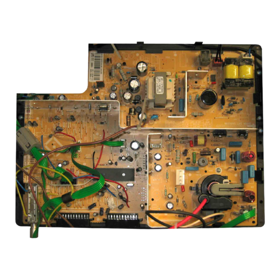
Chassis 14.2
GREENVILLE 7008/5 TOP
GBB3800
SEDANCE 70
ST 70-2405/5 TOP
GBB4400
Advertisement
Table of Contents

Summarization of Contents
Service Manual Overview
Chassis 14.2
Main chassis designation for the service manual.
Greenville 7008/5 TOP Model
Service information for the Greenville 7008/5 TOP model.
Sedance 70 ST 70-2405/5 TOP Model
Service information for the Sedance 70 ST 70-2405/5 TOP model.
General Section
General Notes
Important initial information and precautions before servicing.
Safety Advices
Crucial safety instructions and warnings for safe operation.
Technical Data
Specifications and technical details of the television models.
Operating Hints
Guidance on using the remote control and front panel buttons.
Service and Special Functions
Procedures for accessing and using service mode functions.
Adjustment Procedures
AGC Adjustment
Procedure for adjusting the Automatic Gain Control.
Screen Adjustment
Steps to adjust screen brightness and settings.
Geometry Adjustment
Instructions for adjusting picture geometry settings.
White Balance and Cut off
Procedure for calibrating white balance and cut-off points.
Layout of PCBs and Circuit Diagrams
Chassis Component Layout (Component Side)
Component layout view of the chassis from the component side.
Chassis Component Layout (Solder Side)
Component layout view of the chassis from the solder side.
Chassis - Mains Section Schematic
Schematic diagram of the power supply and mains section.
Chassis - Vertical Deflection Schematic
Schematic diagram of the vertical deflection circuit.
Chassis - Horizontal Deflection Schematic
Schematic diagram of the horizontal deflection circuit.
Chassis - IC101 Part 1 Schematic
Circuit diagram for IC101, Part 1.
Chassis - IC101 Part 2 Schematic
Circuit diagram for IC101, Part 2.
Chassis - IC101 Part 3 Schematic
Circuit diagram for IC101, Part 3.
Chassis - IC301 Part 1 Schematic
Circuit diagram for IC301, Part 1.
Chassis - IC301 Part 2 Schematic
Circuit diagram for IC301, Part 2.
CRT Panel Schematic and Layout
Schematic and layout for the CRT panel.
Keyboard Control Unit Schematic
Circuit diagram and layout for the keyboard control unit.
Power Filter Schematic
Schematic and layout for the power filter.
Oscillograms
Waveforms 1-24
Oscilloscope waveforms for measurement points 1-24.
Waveforms 25-41
Additional oscilloscope waveforms for measurement points 25-41.
DC Voltages
IC101 DC Voltages
DC voltage readings for IC101 pins.
IC301 DC Voltages
DC voltage readings for IC301 pins.
IC303/IC304 DC Voltages
DC voltage readings for IC303/IC304 pins.
IC501 DC Voltages
DC voltage readings for IC501 pins.
IC601 DC Voltages
DC voltage readings for IC601 pins.
IC701 DC Voltages
DC voltage readings for IC701 pins.
Spare Parts Lists
Greenville 7008/5 TOP Spare Parts
List of spare parts for the Greenville 7008/5 TOP model.
Sedance 70 ST 70-2405/5 TOP Spare Parts
List of spare parts for the Sedance 70 ST 70-2405/5 TOP model.
LP-Chassismodul Spare Parts
Spare parts list for the LP-Chassismodul.
Component List
Detailed list of electronic components with part numbers.


Need help?
Do you have a question about the SEDANCE 70 and is the answer not in the manual?
Questions and answers