
Related Manuals for GESTRA NRGS 16-1


Summary of Contents for GESTRA NRGS 16-1
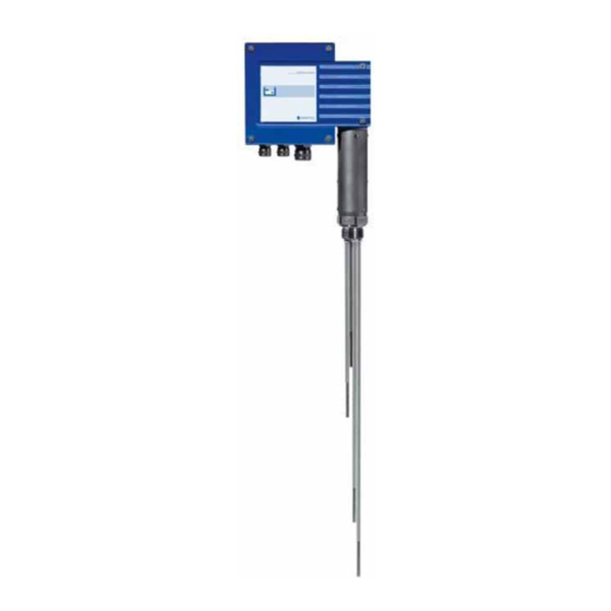
- Page 1 GESTRA Steam Systems NRGS 111 English NRGS 161 NRGS 161S Installation Instructions 81039307 Compact System NRGS 11-1, NRGS 16-1, NRGS 16-1S...
-
Page 2: Table Of Contents
Scope of supply ............................5 Description .............................5 Function ..............................5 Design ..............................5 Technical Data NRGS 11-1, NRGS 16-1, NRGS 16-1 S ....................6, 7 Name plate / marking ..........................8 Dimensions .............................9 Key ...............................12 Design NRGS 11-1, NRGS 16-1, NRGS 16-1 S ....................10 Key ...............................12... - Page 3 Contents continued Page Electrical Connection NRGS 11 -1, NRGS 16 -1, NRGS 16-1 S ....................17 Wiring diagram .............................17 Fill control .............................18 Discharge control ..........................18 Attention ...............................18 Tools ..............................18 Basic Settings Factory setting ............................. 19 Selecting the measuring range ......................19 Attention ...............................19 Tools ..............................19 Commissioning Procedure...
-
Page 4: Important Notes
Important Notes Usage for the intended purpose Use compact system for level monitoring NRGS 11-1, NRGS 16-1 and NRGS 16-1S only for level indication in electrically conductive liquids. Safety note The equipment must only be installed and commissioned by qualified and competent staff. -
Page 5: Explanatory Notes
The compact system NRGS 11-1, NRGS 16-1, NRGS 16-1 S works according to the conductivity measurement system. With the NRGS 11-1, NRGS 16-1 and NRGS 16-1 S a maximum of 4 levels can be signalled in conductive liquids: 4 levels with one switchpoint each ... -
Page 6: Technical Data
Technical Data NRGS 111, NRGS 161, NRGS 161S Type approval NRGS 11-1: TÜV · WR · 11-388 NRGS 16-1: TÜV · WB · 11-388 NRGS 16-1 S: GL 99250-96 HH LR 98/20075 RINA No ELE/30298/1 Operating pressure NRGS 11-1: 6 bar g at 159 °C NRGS 16-1: 32 bar g at 238 °C... -
Page 7: Nrgs 11-1, Nrgs 16-1, Nrgs 16-1 S
M 16 (2) (PG 9) M 20 (1) (PG 16) Protection IP 65 to DIN EN 60529 Max. admissible ambient temperature 70 °C Weight NRGS 11-1: approx. 1.8 kg NRGS 16-1: approx. 1.8 kg NRGS 16-1 S: approx. 2.5 kg... -
Page 8: Name Plate / Marking
24 V 115/230 V 50 / 60 Hz 0,5 / 10 µS/cm 250 V ~ T 2,5 A TÜV . WR . xx-388 GL 99250-96 HH GESTRA AG Münchener Str. 77 D-28215 Bremen Mat-Nr.: Schrift : schwarz Schildgrund : metallic-silber selbstklebende Folie Typ 3M FES 706 wetterfest ie TÜV-Nr. -
Page 9: Dimensions
Technical Data continued Dimensions GESTRA SteamSystems GESTRA NRGS 16-1 b = 70 b = 70 ∅ 42 ∅ 42 Fig. 1 Fig. 2 NRGS 11-1, NRGS 16-1 NRGS 16-1S... -
Page 10: Design
Design NRGS 111, NRGS 161, NRGS 161S Fig. 4 ∅ 1", DIN 228 Fig. 3 Fig. 5... -
Page 11: Functional Elements
Functional Elements NRGS 111, NRGS 161, NRGS 161S Fig. 6 Fig. 7... -
Page 12: Key
Technical Data / Design / Functional Elements Electrode thread 1", DIN 228 Seating surface Joint ring D 33 x 39 DIN 7603 -1.4301 Flange DN 50, PN 40, DIN 2635 Housing screws M4 Cable entry M 16 (PG 9) / M 20 (PG 16) Housing cover Terminal strip PE connection... -
Page 13: Installation
Installation NRGS 111, NRGS 16 1, NRGS 16 1 S 1. Determine required measuring lengths of electrode tips and enter data in table “Functions”. Fig. 3 2. Cut electrode tips 1 , 2 , 3 and 4 accordingly. 3. Deburr faces of electode tips. 4. -
Page 14: Attention
Installation continued Attention The seating surfaces of the standpipe or the flange provided on the vessel must be accurately machined, see Fig. 5 Do not bend electrode tip when mounting. Do not lag electrode body above the hexgonal section. ... -
Page 15: Examples Of Installation
Installation continued Examples of installation 1" 1" DN 50 DN 50 ≤ ≤ 90 ° 90 ° ∅ 20 ∅ 20 Fig. 8 Fig. 9 1" 1" 1" DN 20 DN 100 24,5 24,5 " ≤ 90° DN 20 ∅... -
Page 16: Key
Installation continued Flange PN 40, DN 50, DIN 2527 Flange PN 40, DN 100, DIN 2527 For the approval of the boiler standpipe with connecting flange the relevant regulations must be considered. Vent hole High water (HW) Electrode rod d = 5 mm Protection tube DN 80 Protection tube DN 100 Electrode distance ≥... -
Page 17: Electrical Connection
Electrical Connection NRGS 111, NRGS 16 1, NRGS 16 1 S Flexible multi-core control cable can be used for wiring, min. conductor size 1.5 mm 1. Unscrew screws E and take off housing cover G. Fig. 6 2. Unscrew union nuts of cable entries F. The terminal box can be turned through +/–... -
Page 18: Fill Control
Electrical Connection continued Fill control Mains Fig. 13 Discharge control Mains Fig. 14 Attention Provide supply cables with a slow-blow fuse 250 mA. The connection of the switchpoints 2 and 3 must be effected on site (pump contactor, auxiliary relay)! Tools Screwdriver for cross head screws, size 1... -
Page 19: Basic Settings
Basic Settings Factory setting The equipment features the following factory set default value: ≥ µ Measuring range S/cm Selecting the measuring range The measuring range can be switch-selected between ≥ 0.5 µS/cm and ≥ 10 µS/cm by means of the code switch 5: 1. -
Page 20: Commissioning Procedure
Commissioning Procedure Danger The terminal strip of the NRGS 11-1, NRGS 16 -1, NRGS 16 -1S is live during operation. This presents the danger of electric shock! Cut off power supply before mounting or removing the housing cover! Checking electrical connection 1. -
Page 21: Troubleshooting
Troubleshooting Fault finding list for troubleshooting Switchpoint “Highlevel alarm” exceeded – no function Fault: Mains voltage is not applied. Remedy: Switch on power supply and wire equipment in accordance with the wiring diagram. Fault: The thermal fuse has been triggered. Remedy: In case of a defective thermal fuse the mains voltage has not been applied to terminal J. -
Page 22: Exchanging The Electronic Insert, Removing The Compact System
Exchanging the electronic insert, removing the compact system Danger When loosening the compact system steam or hot water might escape! This presents the risk of severe scalding all over the body! It is therefore essential not to dismantle the compact system unless the boiler pressure is verified to be 0 bar. - Page 23 For your Notes...
- Page 24 Agencies all over the world: www.gestra.de GESTRA AG Münchener Straße 77 28215 Bremen Germany Telefon +49 421 3503-0 Telefax +49 421 3503-393 E-mail info@de.gestra.com www.gestra.de 810393-07/04-2017cm (808430-10) · GESTRA AG · Bremen · Printed in Germany...
Need help?
Do you have a question about the NRGS 16-1 and is the answer not in the manual?
Questions and answers