Table of Contents
Advertisement
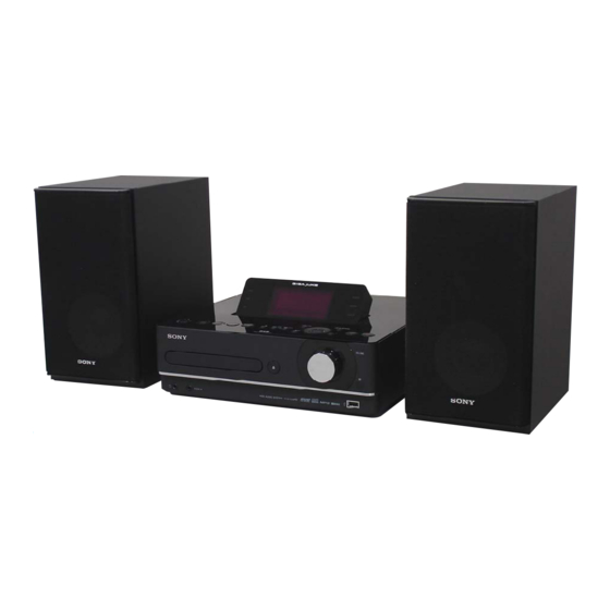
NAS-E35HD/SS-CE
SERVICE MANUAL
Ver. 1.0 2008.05
• SS-CE35HD is the speaker system of
NAS-E35HD.
Trademarks, etc.
You agree that you will use Gracenote Data, the Gracenote
• "GIGA JUKE" and its logo are trademarks of Sony
non-commercial use only. You agree not to assign, copy,
Corporation.
• Title Updater is a trademark of Sony Corporation.
Gracenote Data to any third party. YOU AGREE NOT
• "WALKMAN",
and
are
TO USE OR EXPLOIT GRACENOTE DATA, THE
registered trademarks of Sony Corporation.
GRACENOTE SOFTWARE, OR GRACENOTE SERVERS,
• MICROVAULT is a trademark of Sony Corporation.
EXCEPT AS EXPRESSLY PERMITTED HEREIN.
• MPEG Layer-3 audio coding technology and patents
You agree that your non-exclusive license to use the
•
Servers will terminate if you violate these restrictions.
Media are trademarks or registered trademarks of
If your license terminates, you agree to cease any and
countries.
and Gracenote Servers. Gracenote reserves all rights
•
Gracenote Servers, including all ownership rights. Under
such technology outside of this product is prohibited
no circumstances will Gracenote become liable for any
payment to you for any information that you provide. You
agree that Gracenote, Inc. may enforce its rights under this
• Built with Linter Database.
Agreement against you directly in its own name.
Copyright © 2006-2007, Brycen Corp., Ltd.
Copyright © 1990-2003, Relex, Inc., All rights reserved.
• Music recognition technology and related data are
provided by Gracenote®. Gracenote is the industry
service to count queries without knowing anything about
standard in music recognition technology and related
who you are. For more information, see the web page for
content delivery. For more information, please visit
the Gracenote Privacy Policy for the Gracenote service.
www.gracenote.com.
CD and music-related data from Gracenote, Inc.,
Data are licensed to you "AS IS. " Gracenote makes
no representations or warranties, express or implied,
regarding the accuracy of any Gracenote Data from in
service may practice one or more of the following U.S.
the Gracenote Servers. Gracenote reserves the right to
Patents: #5,987,525; #6,061,680; #6,154,773, #6,161,132,
delete data from the Gracenote Servers or to change data
#6,230,192, #6,230,207, #6,240,459, #6,330,593, and
other patents issued or pending. Some services supplied
under license from Open Globe, Inc. for U.S. Patent:
Gracenote Servers are error-free or that functioning
#6,304,523.
Gracenote and CDDB are registered trademarks of
uninterrupted. Gracenote is not obligated to provide you
with new enhanced or additional data types or categories
the "Powered by Gracenote" logo are trademarks of
that Gracenote may provide in the future and is free to
Gracenote.
discontinue its services at any time.
GRACENOTE DISCLAIMS ALL WARRANTIES
EXPRESS OR IMPLIED, INCLUDING, BUT
NOT LIMITED TO, IMPLIED WARRANTIES OF
MERCHANTABILITY, FITNESS FOR A PARTICULAR
PURPOSE, TITLE, AND NON-INFRINGEMENT.
GRACENOTE DOES NOT WARRANT THE RESULTS
Gracenote® End User License
THAT WILL BE OBTAINED BY YOUR USE OF THE
Agreement
GRACENOTE SOFTWARE OR ANY GRACENOTE
SERVER. IN NO CASE WILL GRACENOTE BE LIABLE
FOR ANY CONSEQUENTIAL OR INCIDENTAL
Gracenote, Inc. of Emeryville, California ("Gracenote").
DAMAGES OR FOR ANY LOST PROFITS OR LOST
REVENUES.
including name, artist, track, and title information
("Gracenote Data") from online servers or embedded
this manual are generally the trademarks or registered
databases (collectively, "Gracenote Servers") and to
trademarks of the manufacturer.
perform other functions. You may use Gracenote Data
™ and ® marks are omitted in this manual.
only by means of the intended End-User functions of this
application or device.
Sony Corporation
9-889-128-01
2008E05-1
Audio Business Group
©
2008.05
Published by Sony Techno Create Corporation
CD Section
HD Section
European model:
DIN power output (rated):
24 + 24 W (8 Ω at 1 kHz, DIN)
Continuous RMS power output
(reference):
30 + 30 W (8 Ω at 1 kHz, 10 % THD)
Music Power output (reference):
30 + 30 W (8 Ω at 1 kHz, 10 % THD)
Other models:
DIN power output (rated):
24 + 24 W (8 Ω at 1 kHz, DIN)
Continuous RMS power output
(reference):
30 + 30 W (8 Ω at 1 kHz, 10 % THD)
HDD Jukebox section
Capacity:
80 GB*
* A portion of the memory is used
for system management functions.
Actual available memory is approx.
72 GB.
names and product names indicated in
Model Name Using Similar Drive
Optical Pick-up Block Name
Model Name Using Similar Drive
Hard Disc Drive Name
SPECIFICATIONS
Recording system:
MP3
Maximum recording time (measured
with MP3 128 kbps):
About 1,300 h
Maximum number of tracks:
20,000
Maximum number of albums:
2,000
CD player section
System:
Compact disc and digital audio
system
Laser Diode Properties:
Emission duration: continuous
Laser Output*: Less than 44.6 μw
*
at a distance of 200 mm from the
objective lens surface on the Optical
Pick-up Block with 7 mm aperture.
Frequency response:
20 Hz - 20 kHz
HDD AUDIO SYSTEM
35HD
AEP Model
UK Model
E Model
Australian Model
NEW
KSM215DHAP
NEW
HDD/SG-NIGHTHAWK-S (80GB)
USB section
Supported bit rate
MP3 (MPEG-1 Audio Layer3):
32 - 320 kbps, VBR
WMA:
48 - 192 kbps, VBR
AAC:
48 - 320 kbps
Sampling frequencies
MP3 (MPEG-1 Audio Layer3):
32/44.1/48 kHz
WMA:
44.1 kHz
AAC:
44.1 kHz
– Continued on next page –
NAS-E35HD
SS-CE35HD
SPEAKER SYSTEM
Advertisement
Table of Contents

Related Manuals for Sony SS-CE35HD


Summarization of Contents
SERVICING NOTES
NOTES ON HANDLING THE OPTICAL PICK-UP BLOCK OR BASE UNIT
Instructions for handling delicate optical pickup blocks safely during repair.
NOTES ON LASER DIODE EMISSION CHECK
Safety precautions and procedure for checking laser diode emission from the pickup block.
UNLEADED SOLDER
Information on using unleaded solder, its characteristics, and handling precautions.
RELEASING THE DISC TRAY LOCK
Procedure to unlock the CD disc tray for demonstration or display purposes.
MODEL IDENTIFICATION
Details on identifying different model versions and their power specifications.
GENERAL
REMOTE CONTROL OVERVIEW
Description of the remote control buttons and their functions for operating the unit.
DISASSEMBLY
DISASSEMBLY FLOW
Step-by-step guide outlining the sequence for disassembling the unit.
PANEL (SIDE L/R) DISASSEMBLY
Instructions for removing the left and right side panels of the unit.
TOP PANEL BLOCK DISASSEMBLY
Procedure for disassembling the top panel section of the main unit.
FRONT PANEL ASSEMBLY DISASSEMBLY
Steps for disassembling the front panel assembly, including HP jack and key boards.
POWER BOARD REPLACEMENT
Procedure for accessing and removing the power supply board.
FL BLOCK DISASSEMBLY
Steps for disassembling the Fluorescent (FL) block.
DISPLAY BOARD REPLACEMENT
Procedure for removing and replacing the display board.
TUNER SECTION BOARDS DISASSEMBLY
Steps for disassembling DAB, DMP, and FM/AM tuner boards.
MAIN BOARD REPLACEMENT
Procedure for accessing and removing the main control board.
CD MECHANISM BLOCK REPLACEMENT
Steps for disassembling and removing the CD mechanism.
USB MICOM BOARD REPLACEMENT
Procedure for accessing and removing the USB MICOM board.
HDD ASSY REPLACEMENT
Steps for removing the Hard Disk Drive assembly.
BASE UNIT DISASSEMBLY
Procedure for disassembling the base unit.
BELT REPLACEMENT
Instructions for replacing the belt in the loading mechanism.
OP BASE ASSY (KSM215DHAP) REPLACEMENT
Procedure for removing the optical pickup base assembly.
TEST MODE
COLD RESET PROCEDURE
Steps to reset the unit to factory default settings, clearing all preset data.
PANEL TEST MODE ACTIVATION
Procedure to enter panel test mode for checking LEDs and display segments.
VERSION CHECK MODE
How to display software versions and MC/destination information.
KEY TEST MODE ACTIVATION
Procedure to enter key test mode for checking button and dial operations.
CD SHIP MODE OPERATION
How to use CD ship mode for optional CD sled motor control, e.g., for cleaning.
CD TRAY LOCK MODE
Procedure for enabling and disabling the CD tray lock function for anti-theft.
CD POWER MANAGE MODE
How to switch the CD power supply on/off for power management.
AM TUNING INTERVAL CHANGE-OVER
Procedure to change AM tuning interval between 9 kHz and 10 kHz for specific models.
CD SHIP AND COLD RESET
Combined procedure for CD ship mode and cold reset operations.
COMMON TEST MODE OPERATION
Steps to enter and operate the common test mode for system checks.
HDD TEST MODE OPERATIONS
How to access and perform various HDD tests and initializations.
HDD TITLE UPDATE TEST MODE
Procedure for checking and updating title information in the HDD.
HDD FACTORY SHIPMENT TEST MODE
How to initialize HDD user areas and perform a cold reset for factory shipment.
ELECTRICAL CHECKS
CD SECTION ELECTRICAL CHECKS
Procedures for checking CD section electrical performance and signal levels.
TUNER SECTION ELECTRICAL CHECKS
Procedures for checking tuner section electrical performance.
DIAGRAMS
BLOCK DIAGRAMS
Overall block diagrams showing system architecture and signal paths.
PRINTED WIRING BOARDS
Component layout diagrams for various boards within the unit.
SCHEMATIC DIAGRAMS
Detailed circuit diagrams for the unit's various boards.
WAVEFORM EXAMPLES
Displays characteristic waveforms from various ICs for diagnostic purposes.
EXPLODED VIEWS
PANEL SECTION EXPLODED VIEW
Exploded view showing the assembly of the unit's panels.
TOP PANEL SECTION EXPLODED VIEW
Exploded view detailing the assembly of the top panel section.
MAIN SECTION EXPLODED VIEW
Exploded view of the main internal components and their assembly.
HDD SECTION EXPLODED VIEW
Exploded view illustrating the assembly of the HDD unit.
CHASSIS SECTION EXPLODED VIEW
Exploded view showing the assembly of the main chassis components.
LOADING MECHANISM SECTION EXPLODED VIEW
Exploded view of the CD loading mechanism assembly.
BASE UNIT SECTION EXPLODED VIEW
Exploded view showing the assembly of the base unit.
SPEAKER SECTION EXPLODED VIEW
Exploded view of the SS-CE35HD speaker system assembly.
ELECTRICAL PARTS LIST
CD SECTION COMPONENTS
List of electrical parts for the CD section, categorized by component type.
MAIN BOARD COMPONENTS
List of electrical parts for the main board, categorized by component type.
USB MICOM BOARD COMPONENTS
List of electrical parts for the USB MICOM board, categorized by component type.
POWER BOARD COMPONENTS
List of electrical parts for the power board, categorized by component type.
Need help?
Do you have a question about the SS-CE35HD and is the answer not in the manual?
Questions and answers