Table of Contents
Advertisement
SERVICE MANUAL
Ver 1.0 2003. 05
• CMT-CQ1 is composed of following models.
As for the service manual, it is issued for each component
model, then, please refer to them.
COMPONENT MODEL NAME
COMPACT DISK DECK
RECEIVER SYSTEM
SPEAKER SYSTEM
SPECIFICATIONS
General
Power requirements
North American model:
120 V AC, 60 Hz
European model:
230 V AC, 50/60 Hz
Australian model:
230 V AC, 50/60 Hz
Mexican model:
120 V AC, 60 Hz
Korean model:
220 V AC, 60 Hz
Taiwan model:
120 V AC, 50/60 Hz
Hong Kong model:
220 V AC, 50/60 Hz
Other models:
230 V AC, 50/60 Hz
Power consumption
North American and Mexican models:
40 watts
European model:
40 watts
0.35 watts (in the standb y
mode)
Other models:
40 watts
Approx. 190 × 120 × 235
Dimensions (w/h/d)
mm incl. projecting parts
and controls
Mass
Approx. 3.5 kg
Supplied accessories
Remote (1)
R6 (size AA) batteries (2)
AM loop antenna (1)
FM lead antenna (1)
Design and specifications are subject to change
without notice.
Sony Corporation
9-877-322-01
2003E1600-1
Home Audio Company
© 2003.05
Published by Sony Engineering Corporation
• Abbreviation
CMT-CQ1
AUS : Australian model.
CND : Canadian model.
HCD-CQ1
HK : Hong Kong model.
KR : Korean model.
SS-CCQ1
PARTS LIST
Part No.
1-477-884-11 COMMANDER, STANDARD (RM-SCQ1)(FOR WHITE)
1-477-884-21 COMMANDER, STANDARD (RM-SCQ1)(FOR BLACK)
1-501-374-72 ANTENNA, LOOP (AM)
0 1-770-019-11 ADAPTER CONVERSION 3P(UK,HK)
1-793-184-22 CONNECTOR (F TYPE ADAPTOR)(FM)
4-228-952-11 COVER, BATTERY (FOR RM-SCQ1)(FOR WHITE)
4-228-952-21 COVER, BATTERY (FOR RM-SCQ1)(FOR BLACK)
4-244-819-11 MANUAL, INSTRUCTION (ENGLISH)
4-244-819-21 MANUAL, INSTRUCTION (FRENCH)(US,CND)
4-244-819-31 MANUAL, INSTRUCTION (FRENCH,SPANISH)(AEP,SP,MX)
4-244-819-41 MANUAL, INSTRUCTION
4-244-819-51 MANUAL, INSTRUCTION (TRADITIONAL CHINESE)
4-244-819-61 MANUAL, INSTRUCTION (KOREAN)(KR)
The components identified by
mark 0 or dotted line with mark
0 are critical for safety.
Replace only with part number
specified.
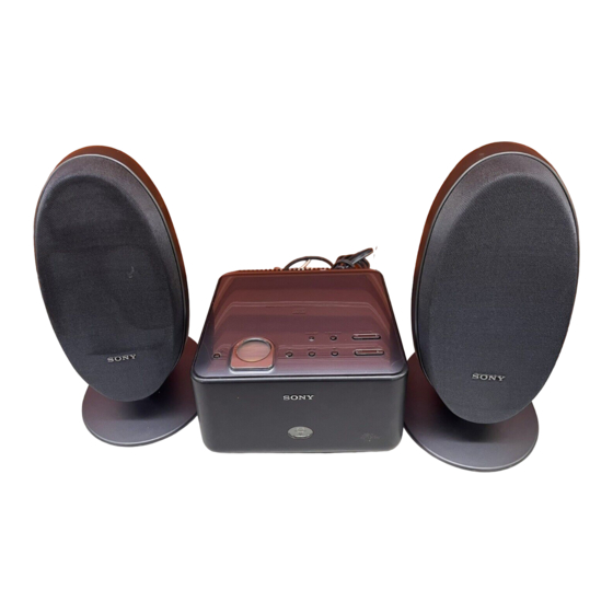
MICRO HI-FI COMPONENT SYSTEM
CMT-CQ1
Canadian Model
Australian Model
MX : Mexican model.
SP
: Singapore model.
TW : Taiwan model.
Description
ACCESSORIES
************
(US,CND,AEP,UK,HK,SP,TW,AUS)
(GERMAN,DUTCH,ITALIAN,SWEDISH,POLISH)(AEP)
Les composants identifiés par
une marque 0 sont critiques
pour la sécurité.
Ne les remplacer que par une
pièce portant le numéro spécifié.
US Model
AEP Model
UK Model
E Model
Remark
(HK,SP,TW)
Advertisement
Table of Contents

Related Manuals for Sony SS-CCQ1


Summary of Contents for Sony SS-CCQ1
- Page 1 0 are critical for safety. pour la sécurité. Replace only with part number Ne les remplacer que par une specified. pièce portant le numéro spécifié. MICRO HI-FI COMPONENT SYSTEM Sony Corporation 9-877-322-01 2003E1600-1 Home Audio Company © 2003.05 Published by Sony Engineering Corporation...
- Page 2 CMT-CQ1 REVISION HISTORY Clicking the version allows you to jump to the revised page. Also, clicking the version at the upper right on the revised page allows you to jump to the next revised page. Ver. Date Description of Revision 2003.05...
- Page 3 The following measured at AC 240 V, 50/60 Hz MICRO Hi-Fi COMPONENT SYSTEM DIN power output (rated): 8 + 8 W (6 ohms at 1 kHz, DIN) Sony Corporation 9-877-323-04 2005A16-1 Personal Audio Company © 2005.01 Published by Sony Engineering Corporation...
- Page 4 HCD-CQ1 Ver 1.1 2003.06 SAFETY CHECK-OUT General Power requirements North American model: 120 V AC, 60 Hz After correcting the original service problem, perform the European model: 230 V AC, 50/60 Hz following safety checks before releasing the set to the customer: Australian model: V AC, 50/60 Hz Check the antenna terminals, metal trim, “metallized”...
-
Page 5: Table Of Contents
HCD-CQ1 TABLE OF CONTENTS 1. SERVICING NOTES ······················································· 4 2. GENERAL ·········································································· 6 3. DISASSEMBLY 3-1. Panel (Back) ···································································· 9 3-2. Panel (Top) Assy ··························································· 10 3-3. PANEL Board ······························································· 11 3-4. CD Mechanism Deck (CDM76-K6BD44S) ················· 11 3-5. JACK Board, REG Board ············································· 12 3-6. -
Page 6: Servicing Notes
30 cm away from the objective lens. DIAGRAMMES SCHÉMATIQUES ET LA LISTE DES PIÈCES SONT CRITIQUES POUR LA SÉCURITÉ DE FONCTIONNEMENT. NE REMPLACER CES COMPOSANTS QUE PAR DES PIÈSES SONY Laser component in this product is capable DONT LES NUMÉROS SONT DONNÉS DANS CE MANUEL OU of emitting radiation exceeding the limit for DANS LES SUPPÉMENTS PUBLIÉS PAR SONY. - Page 7 HCD-CQ1 Service position of the Overall CD mechanism PANEL board JACK board CONTROL board TUNER REMOCON board power transformer POWER board Service position of the CD Mechanism Deck...
-
Page 8: General
HCD-CQ1 SECTION 2 This section is extracted GENERAL from instruction manual. List of button locations and reference pages How to use this page Illustration number Use this page to find the location of buttons and other FUNCTION 2 (6, 7, 14, 16) parts of the system that are mentioned in the text. - Page 9 HCD-CQ1 Remote control ALPHABETICAL ORDER BUTTON DESCRIPTIONS ?/1 (power) 1 (4, 5, 9, 11, 16) A – E F – Z m/M (fast forward/rewind) BALANCE 0 (10) FM MODE qk (10) 2 (5, 6) BASS 6 (10) FUNCTION ws (6, 7, 14, 16) ./>...
- Page 10 HCD-CQ1 Inserting two R6 (size AA) Setting the clock batteries into the remote Use buttons on the remote for the operation. Press ?/1 to turn on the system. Press CLOCK/TIMER SET. Press ./> repeatedly to set the hour. Press ENTER or M. Press ./>...
-
Page 11: Disassembly
HCD-CQ1 SECTION 3 DISASSEMBLY • The equipment can be removed using the following procedure. PANEL (BACK) PANEL (TOP) ASSY CD MECHANISM DECK PANEL BOARD (CDM76-K6BD44S) TRAY JACK BOARD, BEARING ASSY, OPTICAL PICK-UP SLIDER (R), REG BOARD BUSHING (GUIDE A) (KSM-213DCP/Z-NP) SLIDER (L) TUNER (FM/AM) BD BOARD... -
Page 12: Panel (Top) Assy
HCD-CQ1 3-2. Panel (Top) Assy (Location of the claws.) 2 Insert a screwdriver of 4mm diameter and release the claws by raising the panel (top) assy gently. If the main power cannot be turned on, slide the CDM chassis using a screwdriver in order to raise the panel (top) assy. -
Page 13: Panel Board
HCD-CQ1 3-3. PANEL Board 5 panel (top) assy 4 PANEL board 3 four bushings (PWB) 2 four screws (+PTPWH M2.6) 1 two screws (+BTP 2 × 4) 3-4. CD Mechanism Deck (CDM76-K6BD44S) 5 CD mechanism deck 1 screw (+BVTP 3 × 8) (CDM76-K6BD44S) 3 FFC 21p (150) 4 connector (CN1) -
Page 14: Jack Board, Reg Board
HCD-CQ1 3-5. JACK Board, REG Board 1 screw (+BVTP 3 × 8) 3 JACK board 2 FFC 11p (180) 4 screw (+BVTP 3 × 8) 6 REG board 5 connector (CN961) 3-6. Bearing Assy, Bushing (Guide A) 1 screw 2 chassis (+BVTP 3 ×... -
Page 15: Tuner (Fm/Am)
HCD-CQ1 3-7. Tuner (FM/AM) 3 tuner (FM/AM) 6 four screws (+BVTT 3 × 6) 2 FFC 11p (175) 4 connector 7 sub plate (CN902) 1 screw (+BVTP 3 × 8) 5 connector (CN903) 8 power transformer (T901) 3-8. POWER Board 5 screw (+BVTP 3 ×... -
Page 16: Remocon Board, Panel (Front) Assy
HCD-CQ1 3-9. REMOCON Board, Panel (Front) Assy 7 screw 8 panel (side-L) (+BVTP 2.6 × 8) 1 two screws (+BVTP 2.6 × 8) 2 clamp (L35) 3 connector (CN253) 4 two screws (+BVTP 2.6 × 8) 5 REMOCON board 6 panel (front) assy 3-10. -
Page 17: Optical Pick-Up (Ksm-213Dcp/Z-Np)
HCD-CQ1 3-11. Optical Pick-Up (KSM-213DCP/Z-NP) optical pick-up (KSM-213DCP/Z-NP) 8 two insulators 3 insulator 7 two coil springs (insulator) 2 coil spring (insulator) 6 two screws (DIA.12) 5 insulator 1 two screws (DIA.12) 4 coil spring (insulator) 3-12. BD Board optical pick-up (KSM-213DCP/Z-NP) 4 BD board 3 wire (flat type) -
Page 18: Kss-213D/Q-Rp
HCD-CQ1 3-13. KSS-213D/Q-RP 6 KSS-213D/ Q-RP 2 gear (A) 1 claw 5 sled shaft 3-14. Slider (R), Slider (L) 9 screw 8 guide (L) (+PTPWH M2.6) qs slider (L) 7 two screws (+BVTP 2.6 × 8) CDM76-K6BD44S 6 slider (R) q;... -
Page 19: Tray
HCD-CQ1 3-15. Tray 1 magnet assy 3 Rotate the pulley (LDG) in the direction of arrow A . 5 tray 2 pulley (AT) assy 3-16. LOADING Board, Gear (P), Gear (M) 4 stop ring 2.0 type-E 1 belt (CDM55) 5 pulley (LDG) 6 screw 9 torsion spring (+PTPWH M2) -
Page 20: Test Mode
HCD-CQ1 SECTION 4 TEST MODE [MC TEST MODE] [CD SERVICE MODE] • This mode is used to check operations of Amplifier. • This mode can run the CD sled motor freely. Use this mode, for Procedure: instance, when cleaning the optical pick-up. 1. - Page 21 HCD-CQ1 [5 REPEAT OFF MODE] • Number of repeat for CD playback is 5 times when the repeat mode is “REPEAT”. This mode is used to enables CD to repeat playback for limitless times. Procedure: 1. Press the key to turn the power on. [FUNCTION] 2.
-
Page 22: Electrical Adjustments
HCD-CQ1 SECTION 5 ELECTRICAL ADJUSTMENT Checking Location: CD SECTION – BD BOARD (Conductor Side) – Note: CD Block is basically constructed to operate without adjustment. Use YEDS-18 disc (3-702-101-01) unless otherwise indicated. Use an oscilloscope with more than 10 MΩ impedance. Clean the object lens by an applicator with neutral detergent when the signal level is low than specified value with the following checks. -
Page 23: Diagrams
HCD-CQ1 SECTION 6 DIAGRAMS 6-1. Note for Printed Wiring Boards and Schematic Diagrams • Circuit Boards Location THIS NOTE IS COMMON FOR PRINTED WIRING BOARDS AND SCHEMATIC DIAGRAMS. (In addition to this, the necessary note is printed in each block.) For schematic diagrams. -
Page 24: Block Diagram - Cd Section
HCD-CQ1 6-2. Block Diagram – CD Section – FILTER DIGITAL SIGNAL PROCESSOR, DIGITAL FILTER, D/A CONVERTER IC101 (1/2) RF AMP, 56 53 FOCUS/TRACKING ERROR AMP IC103 A+3.3V PCMD LRCK INTERFACE RFAC C2PO RFAC RFAC RFAC ASYMMETRY DIGITAL SUMMING CORRECTION DEMODULATOR ASYI ASYO L-CH... -
Page 25: Block Diagram - Main Section
HCD-CQ1 6-3. Block Diagram – MAIN Section – VOL CONT IC301 J703 R CH J702 R-CH L SELO PC/MD/TAPE OUT PC/MD/TAPE IN LINE L3 R SELO R-CH TUNER L2 MUTE POWER AMP Q604 CD L1 IC801 TUNER PACK SYSTEM CONTROLLER R CH J701 IC101(2/2) -
Page 26: Printed Wiring Board - Bd Section
HCD-CQ1 6-4. Printed Wiring Board – BD Section – • See page 21 for Circuit Boards Location. S101 (LIMIT) ON : WHEN THE OPTICAL PICK-UP M101 BD BOARD IS INNER POSITION (SPINDLE) C159 JW621 JR101 R159 JW609 R158 R197 C146 JW600 S101 C118... -
Page 27: Schematic Diagram - Bd Section
HCD-CQ1 6-5. Schematic Diagram – BD Section – • See page 21 for Wavefoms. • See page 34 for IC Block Diagrams. R196 2.2k R195 330k R194 C193 C194 C109 C111 R109 C198 1500p 100p C116 C183 C184 C185 C165 C146 C130 JR101... -
Page 28: Printed Wiring Board - Panel Section (Component Side)
HCD-CQ1 6-6. Printed Wiring Board – PANEL Section (Component Side) – • : Uses unleaded solder. • See page 21 for Circuit Boards Location. CONTROL BOARD CN102 (Page 28) VOLUME DIMMER FUNCTION D401-403 (BACK LIGHT) TUNING... -
Page 29: Panel Section (Conductor Side)
HCD-CQ1 6-7. Printed Wiring Board – PANEL Section (Conductor Side) – • : Uses unleaded solder. • See page 21 for Circuit Boards Location. LCD401 (LIQUID CRYSTAL DISPLAY) -
Page 30: Printed Wiring Board - Control Section (Component Side)
HCD-CQ1 6-8. Printed Wiring Board – CONTROL Section (Component Side) – • : Uses unleaded solder. • See page 21 for Circuit Boards Location. PANEL BOARD CN401 (Page 26) -
Page 31: Printed Wiring Board - Control Section (Conductor Side)
HCD-CQ1 6-9. Printed Wiring Board – CONTROL Section (Conductor Side) – • : Uses unleaded solder. • See page 21 for Circuit Boards Location. IC501 (LODING) LODING IN /OUT DETECT FOR FLASH MICOM WRITER • Semiconductor Location Ref. No. Location D101 D102 D103... -
Page 32: Schematic Diagram - Control Section
HCD-CQ1 6-10. Schematic Diagram – CONTROL Section – • See page 21 for Wavefoms. • See page 34 for IC Block Diagrams. CN104 C151 C153 R151 CN102 R154 CN401 R421 C152 R152 R422 R423 R424 LCD401 R425 R426 R427 R428 R429 R430 R167... -
Page 33: Printed Wiring Board - Power Section (Component Side)
HCD-CQ1 6-11. Printed Wiring Board – POWER Section (Component Side) – • : Uses unleaded solder. • See page 21 for Circuit Boards Location. -
Page 34: Printed Wiring Board - Power Section (Conductor Side)
D907 (MAIN) CN952 D908 D911 D912 D913 D914 D915 D920 IC301 IC801 SPEAKER IC901 TUNER IC911 PACK (ONLY FOR IC913 SS-CCQ1) IC914 IC961 IC901 Q601 Q602 Q603 Q604 Q605 Q654 Q822 IC914 Q823 CONTROL Q824 BOARD Q901 CN101 Q902 (Page 29) -
Page 35: Schematic Diagram - Power Section
HCD-CQ1 6-13. Schematic Diagram – POWER Section – • See page 34 for IC Block Diagrams. R808 CN801 C803 R801 10 1/2W CONNECTOR R805 L801 1.7uH C807 R802 R807 C808 CN812 R809 C301 C858 C810 C809 C855 C805 10 50V D651 R852 180 1/2W... -
Page 36: Ic Block Diagrams
HCD-CQ1 6-14. IC Block Diagrams – BD Board – – CONTROL Board – IC101 CXD3017Q IC103 CXA2647N-T4 IC251 BA6956AN 59 58 57 46 45 44 ROM/RW Digital DC OFST RFDCI – LRCK – RFDCO OP Amp PCMD Interface CONTROL LOGIC Digital Asymmetry Converter... -
Page 37: Ic Pin Function Description
HCD-CQ1 6-15. IC Pin Function Description • IC101 MB90803PF-G-101-BMD (SYSTEM CONTROLLER) Pin No. Pin Name Description MTR-CTRL1 Motor control signal output to the motor driver (IC251) OUT SW CD tray detection switch signal input IN SW CD tray detection switch signal input SENS SENS signal input from the DSP X-RST... - Page 38 HCD-CQ1 Pin No. Pin Name Description RESET System reset signal input from the reset signal generator ST MUTE Tuner muting signal output STEREO FM stereo detection signal input TUNED Tuner tuned status signal input LCD-ADJ — LCD_ADJ terminal 59 to 62 COM0 to COM3 Common signal output to the liquid crystal display 63, 64...
-
Page 39: Exploded Views
HCD-CQ1 Ver 1.1 2003.06 SECTION 7 EXPLODED VIEWS NOTE: • -XX, -X mean standardized parts, so they may • The mechanical parts with no reference number The components identified by mark 0 or have some differences from the original one. in the exploded views are not supplied. -
Page 40: Chassis Section-1
HCD-CQ1 Ver 1.1 2003.06 7-2. Chassis Section-1 CDM76-K6BD44S not supplied not supplied not supplied supplied not supplied chassis assy Ref. No. Part No. Description Remarks Ref. No. Part No. Description Remarks X-4955-635-1 BEARING ASSY 3-559-407-01 CUSHION, STOPPER 4-218-253-21 SCREW (M2.6), +BTTP 3-378-109-12 CUSHION, SARANET 4-244-753-01 BUSHING (GUIDE A) 7-685-646-71 SCREW +BVTP 3X8 TYPE2 IT-3... -
Page 41: Chassis Section-2
HCD-CQ1 7-3. Chassis Section-2 F901 F911 F912 not supplied T901 Ref. No. Part No. Description Remarks Ref. No. Part No. Description Remarks 1-693-603-31 TUNER (FM/AM)(HK,SP,TW,MX,AUS) * 108 3-703-244-00 BUSHING (2104), CORD 1-693-605-11 TUNER (FM/AM)(AEP,UK,KR) 0 F901 1-533-451-11 FUSE, GLASS TUBE (DIA. 5)(3.15A 125V) 1-693-623-11 TUNER (FM/AM)(FOR BLACK)(US,CND) (US,CND) 0 F901... -
Page 42: Chassis Section-3
HCD-CQ1 Ver 1.1 2003.06 7-4. Chassis Section-3 not supplied not supplied supplied Ref. No. Part No. Description Remarks Ref. No. Part No. Description Remarks X-4955-305-1 PANEL (FRONT) ASSY (WHITE)(US,CND) 1-773-320-11 FFC 31P (150) X-4955-534-1 PANEL (FRONT) ASSY (WHITE) A-4731-456-A CONTROL BOARD, COMPLETE (US,CND) (EXCEPT UC,CND) A-4731-469-A CONTROL BOARD, COMPLETE (AEP,UK) X-4955-644-1 PANEL (FRONT) ASSY (BLACK)(US,CND) -
Page 43: Cd Mechanism Deck Section-1
HCD-CQ1 7-5. CD Mechanism Deck Section-1 (CDM76-K6BD44S) supplied supplied supplied supplied KSM-213DCP/Z-NP Ref. No. Part No. Description Remarks Ref. No. Part No. Description Remarks 4-951-620-01 SCREW (2.6X8), +BVTP X-4955-579-2 MD BASE 4-218-252-11 SCREW (+PTPWH M2.6), FLOATING 4-227-549-11 INSULATOR 4-244-245-01 SLIDER (L) 4-227-045-11 SPRING (INSULATOR), COIL 4-227-899-01 SCREW (DIA. -
Page 44: Cd Mechanism Deck Section-2
HCD-CQ1 Ver. 1.3 7-6. CD Mechanism Deck Section-2 (CDM76-K6BD44S) not supplied supplied Ref. No. Part No. Description Remarks Ref. No. Part No. Description Remarks X-4955-351-2 BRACKET ASSY 4-244-249-01 SPRING, TORSION 4-244-243-01 TRAY 4-244-248-01 LEVER (SW) 4-244-242-01 CHASSIS (CDM) 1-452-925-21 MAGNET ASSY 4-244-821-01 COLLAR X-4953-195-3 PULLEY (AT) ASSY X-4955-351-1 BRACKET ASSY... -
Page 45: Ksm-213Dcp/Z-Np
HCD-CQ1 7-7. KSM-213DCP/Z-NP M102 Ref. No. Part No. Description Remarks Ref. No. Part No. Description Remarks 2-626-908-02 SHAFT, SLED X-2161-802-1 CHASSIS ASSY (DCP), TT 2-646-697-03 SHUTTER (F), LENS 2-627-003-01 GEAR (B) (RP) 2-646-702-02 SPRING, EXTENSION 3-713-786-51 SCREW +P 2X3 0 604 8-820-020-02 OPTCAL PICK-UP (KSS-213D/Q-RP) M102 X-2625-769-1 GEAR ASSY (MB) (RP), MOTOR (SLED) -
Page 46: Electrical Parts List
HCD-CQ1 SECTION 8 ELECTRICAL PARTS LIST NOTE: • Due to standardization, replacements in the • COILS • Abbreviation parts list may be different from the parts uH: µH AUS : Australian model. specified in the diagrams or the components • RESISTORS CND: Canadian model. - Page 47 HCD-CQ1 CONTROL Ref. No. Part No. Description Remarks Ref. No. Part No. Description Remarks R120 1-216-835-11 METAL CHIP 1/16W C153 1-164-156-11 CERAMIC CHIP 0.1uF C154 1-164-156-11 CERAMIC CHIP 0.1uF R122 1-216-845-11 METAL CHIP 100K 1/16W R123 1-216-833-11 METAL CHIP 1/16W C165 1-164-156-11 CERAMIC CHIP 0.1uF...
- Page 48 HCD-CQ1 CONTROL Ref. No. Part No. Description Remarks Ref. No. Part No. Description Remarks FB165 1-216-864-11 METAL CHIP 1/16W R127 1-216-847-11 METAL CHIP 150K 1/16W FB190 1-216-864-11 METAL CHIP 1/16W R128 1-216-826-11 METAL CHIP 2.7K 1/16W FB251 1-216-864-11 METAL CHIP 1/16W R129 1-216-809-11 METAL CHIP...
- Page 49 HCD-CQ1 CONTROL JACK LOADING PANEL Ref. No. Part No. Description Remarks Ref. No. Part No. Description Remarks R207 1-216-829-11 METAL CHIP 4.7K 1/16W 1-786-514-11 SWITCH, LEVER (SLIDE) R208 1-216-813-11 METAL CHIP 1/16W (LODING IN/OUT DETECT) R209 1-216-833-11 METAL CHIP 1/16W ************************************************************ R212 1-216-813-11 METAL CHIP...
- Page 50 HCD-CQ1 PANEL POWER Ref. No. Part No. Description Remarks Ref. No. Part No. Description Remarks R438 1-216-809-11 METAL CHIP 1/16W C358 1-126-163-11 ELECT 4.7uF R439 1-216-809-11 METAL CHIP 1/16W C359 1-126-163-11 ELECT 4.7uF R440 1-216-809-11 METAL CHIP 1/16W R441 1-216-809-11 METAL CHIP 1/16W C360 1-124-261-00 ELECT...
- Page 51 HCD-CQ1 POWER Ref. No. Part No. Description Remarks Ref. No. Part No. Description Remarks CN605 1-568-830-11 CONNECTOR, FFC 11P R313 1-216-809-11 METAL CHIP 1/16W CN801 1-816-048-11 TERMINAL BOARD (SPEAKER) R314 1-216-864-11 METAL CHIP 1/16W 0 CN901 1-564-321-00 PIN, CONNECTOR (3.96mm PITCH) 2P R315 1-216-821-11 METAL CHIP 1/16W...
- Page 52 HCD-CQ1 Ver 1.2 POWER REMOCON Ref. No. Part No. Description Remarks Ref. No. Part No. Description Remarks R907 1-216-821-11 METAL CHIP 1/16W MISCELLANEOUS R908 1-216-821-11 METAL CHIP 1/16W *************** R909 1-216-825-11 METAL CHIP 2.2K 1/16W R910 1-216-864-11 METAL CHIP 1/16W 1-693-603-31 TUNER (FM/AM) (HK,SP,TW,MX,AUS) 0 R911 1-219-119-11 FUSIBLE...
- Page 53 HCD-CQ1 MEMO...
- Page 54 HCD-CQ1 REVISION HISTORY Clicking the version allows you to jump to the revised page. Also, clicking the version at the upper right on the revised page allows you to jump to the next revised page. Ver. Date Description of Revision 2003.05 2003.06 Change of the specifications...
- Page 55 US Model Canadian Model Ver 1.0 2003. 05 AEP Model UK Model E Model Australian Model • SS-CCQ1 is the speaker system in CMT-CQ1. SPECIFICATIONS Speaker system 2 way, bass-reflex type Speaker units Woofer: 10 cm dia., cone type Tweeter: 2.5 cm dia., balanced dome...
- Page 56 SS-CCQ1 EXPLODED VIEW AND PARTS LIST NOTE: • -XX, -X mean standardized parts, so they may • The mechanical parts with no reference number • Abbreviation have some differences from the original one. in the exploded views are not supplied.
- Page 57 SS-CCQ1 MEMO...
- Page 58 SS-CCQ1 REVISION HISTORY Clicking the version allows you to jump to the revised page. Also, clicking the version at the upper right on the revised page allows you to jump to the next revised page. Ver. Date Description of Revision...
Need help?
Do you have a question about the SS-CCQ1 and is the answer not in the manual?
Questions and answers