Table of Contents
Advertisement
Quick Links
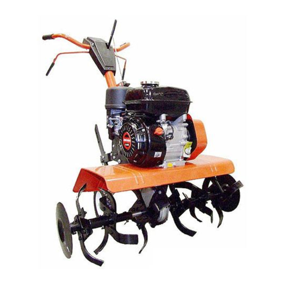
Operator's Manual
Front Tine Tillers
Model Series
340 Thru 390
Model Series 390 Shown
IMPORTANT: READ SAFETY RULES AND INSTRUCTIONS CAREFULLY
Warning:
This unit is equipped with an internal combustion engine and should not be used on or near any unimproved forest-
covered, brush-covered or grass-covered land unless the engine's exhaust system is equipped with a spark arrester meeting
applicable local or state laws (if any). If a spark arrester is used, it should be maintained in effective working order by the operator.
In the State of California the above is required by law (Section 4442 of the California Public Resources Code). Other states may have
similar laws. Federal laws apply on federal lands. A spark arrester for the muffler is available through your nearest engine authorized
service dealer or contact the service department, P.O. Box 361131 Cleveland, Ohio 44136-0019.
MTD LLC, P.O. BOX 361131 CLEVELAND, OHIO 44136-0019
PRINTED IN U.S.A.
770-10135C.fm
FORM NO.
(11/03)
Advertisement
Table of Contents

Related Manuals for MTD 360


Summary of Contents for MTD 360
- Page 1 Federal laws apply on federal lands. A spark arrester for the muffler is available through your nearest engine authorized service dealer or contact the service department, P.O. Box 361131 Cleveland, Ohio 44136-0019. MTD LLC, P.O. BOX 361131 CLEVELAND, OHIO 44136-0019 PRINTED IN U.S.A.
-
Page 2: Table Of Contents
This information will be necessary to use the manufacturer’s web site and/or help from the Customer Support Department or an authorized service dealer. Copy the model number here: Copy the serial number here: MTD LLC P. O. BOX 361131 CLEVELAND,OH 44136 330-220-4683 www.mtdproducts.com... -
Page 3: Important Safe Operation Practices
SECTION 1: IMPORTANT SAFE OPERATION PRACTICES WARNING: This symbol points out important safety instructions which, if not followed, could endanger the personal safety and/or property of yourself and others. Read and follow all instructions in this manual before attempting to operate this machine. Failure to comply with these instructions may result in personal injury. - Page 4 Look down and behind and use care when in Do not change the engine governor settings or reverse or pulling machine towards you. over-speed the engine. The governor controls the Start the engine according to the instructions found maximum safe operating speed of the engine. in this manual and keep feet well away from the Maintain or replace safety and instruction labels, as tines at all times.
-
Page 5: Assembling Your Tiller
SECTION 2: ASSEMBLING YOUR TILLER NOTE: This operator’s guide covers three different model tillers. Model series 340 thru 345 have forward Tailpiece tine drive only. Model series 390 has both forward and reverse tine drive. Follow only the instructions which pertain to your model tiller. - Page 6 • Loosen the hex nut on the threaded rod near the Handle end of the cable, and move it up the rod as far as it will go. • Unthread the rod from the rest of the cable. Hook Bell Carriage Bolt the “Z”...
-
Page 7: Know Your Tiller
• Disconnect the spark plug wire and move it away assembly). Unthread the rod from the cable 2 or 3 from the spark plug to prevent accidental starting. turns. Retighten the hex nut, and check again for • Engage and release the tine engagement handle, correct adjustment. -
Page 8: Operating Your Tiller
Depth Stake Tines And End Caps The depth stake controls the tilling depth. Refer to The tilling tines and end caps (are used to cultivate, OPERATING YOUR TILLER in Section 4. furrow, and prepare your garden for seeding. The end caps (Model Series 390 only) are used to avoid tilled soil from overflowing onto unwanted areas. - Page 9 Removing End Caps • Stand at side of tiller. Grasp the starter handle and (Model Series 390 only) pull out slowly, until it pulls slightly harder. Let rope The end cap, which are used to avoid tilled soil from rewind slowly. overflowing onto unwanted areas, are removable from •...
- Page 10 Handle Pressure Transport Further control of tilling depth and travel speed can be Position obtained by variation of pressure on the handles. Depth Stake • A downward pressure on the handles will reduce the working depth and increase the forward speed. •...
-
Page 11: Making Adjustments
organic matter will substantially increase the fertility of your garden. For proper decaying action, fertilizer should be applied and worked in with the mulch materials. Breaking up leaves and straw and mixing it with several inches of soil causes the soil to hold moisture longer and allows proper aeration of the plant root system. -
Page 12: Belt Replacement
Maintain engine oil as instructed in the separate • Remove the hex stop nut and flat washer from the engine manual packed with your unit. Read and follow side of the belt cover. Remove belt cover. instructions carefully. Lock Nut & Hex Washer Service air cleaner every ten hours under normal Screw... - Page 13 Off-Season Storage • Reassemble the new belt, following instructions in reverse order. Make certain the forward drive belt is If the tiller will not be used for a period longer than 30 assembled with the wide side of the belt away from days, the following steps should be taken to prepare the the transmission and engine pulleys.
-
Page 14: Troubleshooting
SECTION 7: TROUBLE SHOOTING GUIDE Trouble Possible Cause(s) Corrective Action Engine fails to Fuel tank empty, or stale fuel. Fill tank with clean, fresh gasoline. Fuel will not last over start thirty days unless a fuel stabilizer is used. Throttle control lever not in correct Move throttle lever to start position. - Page 15 NOTES...
-
Page 16: Illustrated Parts List
SECTION 8: ILLUSTRATED PARTS LIST Model Series 340 Thru 345 Standard Briggs & Stratton Tecumseh Engines... - Page 17 Model Series 340 Thru 345 Ref. Ref. Part No. Part Description Part No. Part Description 712-0442 Acorn Lock Nut 1/4-20 711-1036 Spec. Hex Nut 736-3020 Flat Washer.271” I.D. x.630” O.D. 736-0119 L-Wash. 5/16” I.D. 731-1599 Handle Cover 710-3008 Hex Bolt 5/16-18 Gr. 5 712-0287 Hex Nut 1/4-20 Gr.2 786-0129...
- Page 18 Model Series 340 Thru 345...
- Page 19 Model Series 340 Thru 345 Ref. Ref. Part No. Part Description Part No. Part Description 712-0392 Hex L-Stop nut 1/4-28 746-0918 Forward Clutch Cable 736-3020 Flat Wash.266” I.D. X.625” O.D. 786-0053 Tine Shield Bracket 736-0171 L-Wash. 7/16” I.D. 710-0599 Hex Washer Screw 1/4-20 x.5” 712-0240 Hex Nut 7/16-20 Thd.
- Page 20 Model Series 390 ††Standard Briggs & Stratton Tecumseh Engines 51†† 52†† 53††...
- Page 21 Model Series 390 REF. REF. PART NO. DESCRIPTION PART NO. DESCRIPTION 736-0242 Wash. Bell.340” I.D. x.872” O.D. 712-0442 Acorn Lock Nut 1/4-20 711-1036A Spec. Hex Nut 736-3020 Flat Washer.271” I.D. x.630” O.D. 736-0119 L-Wash. 5/16” I.D. 720-0270A Reverse Handle Grip 710-3008 Hex Bolt 5/16-18 Gr.
- Page 22 Model Series 390 †††Honda Engine...
- Page 23 Model Series 390 REF. REF. PART NO. DESCRIPTION PART NO. DESCRIPTION 748-0350 Pulley Mounting Adapter 712-0392 Hex L-Stop nut 1/4-28 736-0112 Bell-Wash.525” I.D. x 1.5” O.D. 736-3020 Flat Wash.266” I.D. x.625” O.D. 712-3029 Hex Jam Nut 1/2-20 Thd. (Gr. 5) 710-0599 Hex Washer TT-Tap Scr.
-
Page 24: Warranty
MANUFACTURER’S LIMITED WARRANTY FOR: The limited warranty set forth below is given by MTD LLC with MTD does not extend any warranty for products sold or respect to new merchandise purchased and used in the exported outside of the United States, its possessions United States, its possessions and territories.
Need help?
Do you have a question about the 360 and is the answer not in the manual?
Questions and answers