Advertisement
Quick Links
DCR-DVD110E/DVD115E/DVD310E/DVD410E/DVD610/
DVD610E/DVD710/DVD710E/DVD810/DVD810E
SERVICE MANUAL
Ver. 1.3 2008.11
Revision History
Revision History
Revised-1
Replace the previously issued
SERVICE MANUAL 9-852-249-12
with this manual.
Link
Link
MODEL INFORMATION TABLE
SCHEMATIC DIAGRAMS
The components identified by
mark 0 or dotted line with
mark 0 are critical for safety.
Replace only with part num-
ber specified.
DCR-DVD110E/DVD115E/DVD310E/DVD410E/DVD610/
DVD610E/DVD710/DVD710E/DVD810/DVD810E_L3
9-852-249-13
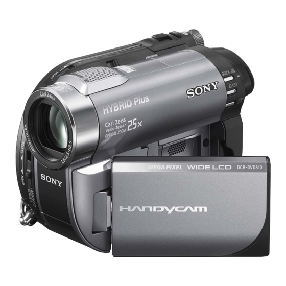
Photo: DCR-DVD810
PRINTED WIRING BOARDS
Les composants identifiés par une
marque 0 sont critiques pour la
sécurité.
Ne les remplacer que par une pièce
portant le numéro spécifié.
Sony EMCS Co.
DIGITAL VIDEO CAMERA RECORDER
RMT-835
LEVEL
US Model
Canadian Model
AEP Model
UK Model
East European Model
North European Model
E Model
Australian Model
Hong Kong Model
Chinese Model
Korea Model
Argentine Model
Brazilian Model
Thai Model
Tourist Model
Japanese Model
REPAIR PARTS LIST
Published by Kohda TEC
3
2008K0500-1
© 2008.11
Advertisement

Summarization of Contents
Model Information Table
Non-MEGA Model Specifications
Specifications table for non-MEGA models, including destination and features.
MEGA Model Specifications
Specifications table for MEGA models, including destination and features.
Model Abbreviations
Key to abbreviations for country/region codes used in model tables.
Schematic Diagrams
VC-520 Board (1/20) - A/D Converter, Timing Generator
Schematic for board 1/20, covering A/D Converter & Timing Generator.
VC-520 Board (7/20) - CPU (Power Supply)
Schematic for board 7/20, detailing the CPU Power Supply section.
VC-520 Board (12/20) - DVD Mecha Drive
Schematic for board 12/20, detailing the DVD Mecha Drive components.
VC-520 Board (15/20) - Video, Audio I/O
Schematic for board 15/20, covering Video and Audio I/O circuits.
Printed Wiring Boards
VC-520 Board Side A Layout
Printed wiring board layout for Side A, showing component placement.
VC-520 Board Side B Layout
Printed wiring board layout for Side B, showing component placement.
Repair Parts List
Electrical Components Listing
Detailed list of electrical parts like capacitors, resistors, transistors, and ICs.
Connectors, Fuses, and Other Parts
List of connectors, fuses, inductors, and other miscellaneous parts.


Need help?
Do you have a question about the handycam DCR-DVD610E and is the answer not in the manual?
Questions and answers