Table of Contents
Advertisement
Quick Links
AUDIO/VIDEO MULTI-CHANNEL RECEIVER
VSX-AX4AVi-S
VSX-AX2AV-S
THIS MANUAL IS APPLICABLE TO THE FOLLOWING MODEL(S) AND TYPE(S).
Model
Type
VSX-AX4AVi-S
HYXJ
VSX-AX2AV-S
HYXJ
*:Alter the wiring of the power-supply block at the primary winding of Power transformer referring to the Line Voltage Selection
described in this Service Manual ("4.19 TRANS1 and PRIMARY ASSYS").
For details, refer to "Important Check Points for Good Servicing".
PIONEER CORPORATION
PIONEER ELECTRONICS (USA) INC. P.O. Box 1760, Long Beach, CA 90801-1760, U.S.A.
PIONEER EUROPE NV Haven 1087, Keetberglaan 1, 9120 Melsele, Belgium
PIONEER ELECTRONICS ASIACENTRE PTE. LTD. 253 Alexandra Road, #04-01, Singapore 159936
PIONEER CORPORATION 2005
STANDBY/ON
PHASE
MCACC
CONTROL
POSITION
INPUT
SELECTOR
Power Requirement
AC220-230V
AC220-230V
4-1, Meguro 1-chome, Meguro-ku, Tokyo 153-8654, Japan
AUDIO/VIDEO MULTI-CHANNEL RECEIVER
PHASE
CONTROL
DIGITAL PRECISION
PROCESSING
AUTO SURR/
HOME
STREAM DIRECT
THX
VSX-AX4AVi-S
The voltage can be converted by the
AC240V, *
AC240V, *
VSX-AX4AVi
STANDARD
ADVANCED
SURROUND
SURROUND
MASTER
VOLUME
ORDER NO.
RRV3261
following method.
T-ZZK OCT. 2005 printed in Japan
Advertisement
Table of Contents
Troubleshooting

Related Manuals for Pioneer VSX-AX2AV-S


Summarization of Contents
Safety Information and Precautions
SAFETY PRECAUTIONS
Precautions for customer and technician protection.
PRODUCT SAFETY NOTICE
Electrical and mechanical parts have special safety characteristics.
Important Servicing Checkpoints
SERVICING PROCEDURES
Product safety, adjustments, cleaning, and shipping procedures.
Specifications and Accessories
PERFORMANCE SPECIFICATIONS
Continuous power output, audio section, tuner, and miscellaneous specs.
FURNISHED PARTS
List of accessories included with the unit.
Accessories
LIST OF ACCESSORIES
AM loop antenna, FM wire antenna, AC power cord, iPod cable, remote, mic, batteries.
Internal Structure and Diagrams
EXPLODED VIEWS AND PARTS LISTS
Exploded views and parts lists for various sections.
CHASSIS SECTION
Exploded view and parts list for the chassis section.
POWER AMP BLOCK
Exploded view and parts list for the power amplifier block.
FRONT PANEL SECTION
Exploded view and parts list for the front panel section.
BLOCK DIAGRAMS
Block diagrams illustrating the unit's overall and specific functional blocks.
SCHEMATIC DIAGRAMS
Schematic diagrams for various internal assemblies and circuits.
PCB CONNECTION DIAGRAMS
Diagrams showing PCB interconnections between major assemblies.
PCB PARTS LISTS
List of all PCB assemblies with their corresponding part numbers.
Troubleshooting
GENERAL INFORMATION
General information including diagnosis procedures and test modes.
TROUBLESHOOTING THE DSP BLOCK
Step-by-step troubleshooting guide for issues related to the DSP block.
DIAGNOSIS OF THE HDMI BLOCK
Procedures for diagnosing HDMI block issues and related systems.
DIAGNOSIS OF THE 1394 ASSY
Diagnostic procedures for the 1394 Assy (i.LINK) interface.
Maintenance and Updates
HOW TO UPDATE THE DSP FLASH ROM
Step-by-step instructions for updating DSP flash ROM via CD.
DISASSEMBLY
Procedures for disassembling the unit, including power amp block removal.
FAILURE DIAGNOSIS OF THE POWER AMP BLOCK
Diagnosing failures in the current and voltage amplifier blocks.
Panel Facilities
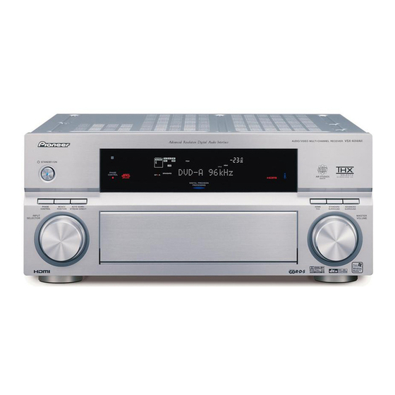
FRONT PANEL OVERVIEW
Illustration and explanation of the front panel controls and indicators.
REMOTE CONTROL
Explanation of remote control functions and operating range.
Need help?
Do you have a question about the VSX-AX2AV-S and is the answer not in the manual?
Questions and answers