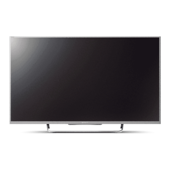
Table of Contents
Advertisement
HISTORY INFORMATION FOR THE FOLLOWING MANUAL:
SERVICE MANUAL (COMMON)
SERVICE MANUAL (COMMON)
Version
Date
Subject
1
01/2014
1
st
Issue.
RB2G
CHASSIS
Segment: HE-L
LCD TV
LCD TV
9-888-147-01
For SM - Unique , please refer :
For SM Unique please refer :
9-888-147-A1 ( America )
9-888-147-C1 ( China)
9-888-147-E1 ( Europe )
9-888-147-P1 ( Pan Asia )
Advertisement
Table of Contents

Summarization of Contents
SECTION 1 SAFETY NOTES
1-1. Warnings and Caution
General safety warnings and precautions for service personnel.
1-2. Caution Handling of LCD Panel
Specific safety guidelines for handling the LCD panel during service.
1-3. Caution About the Lithium Battery
Precautions regarding the replacement and handling of lithium batteries.
1-4. Safety Check-Out
Essential safety checks to perform after completing repairs.
1-5. Leakage Test
Procedures and limits for AC leakage testing.
1-6. How to Find a Good Earth Ground
Methods for identifying and verifying a proper earth ground connection.
1-7. Lead Free Information
Information on lead-free solder usage and board identification.
1-8. Handling the FLEXIBLE FLAT CABLE (FFC)
Proper techniques for inserting and removing FFCs to prevent damage.
SECTION 2 SELF DIAGNOSTIC FUNCTION
2-1. Overview of Control Buttons
Basic identification and function of TV control buttons for different regions.
2-2. LED Display Control
Explanation of LED indicators and their meanings for TV status.
2-3. LED Pattern
Description of specific LED blinking patterns indicating operational states.
2-4. Standby LED Error Display
Details on how the standby LED indicates specific error conditions.
2-5. Triage Chart
A chart to help diagnose problems based on LED blinking codes.
SECTION 3 TROUBLE SHOOTING
3-1. NO POWER
Troubleshooting steps for scenarios where the TV does not power on.
3-2. LED BLINKING
Interpretation of LED blinking patterns for diagnosing TV errors.
3-3. No Sound
Diagnostic procedures for troubleshooting audio issues.
3-4. NO PICTURE
Troubleshooting guide for issues related to the absence of a video signal.
3-5. SIDE BUTTONS MALFUNCTION
Steps to diagnose and resolve issues with the TV's physical side buttons.
3-6. IR REMOTE COMMANDER MALFUNCTION
Procedures for troubleshooting remote control response problems.
3-7. Light Sensor Error
Steps to diagnose and fix errors related to the ambient light sensor.
3-8. Network Malfunction: Ethernet (Wired)
Troubleshooting guide for wired network connectivity problems.
3-9. 3D-Glasses (Active) malfunction
Diagnostic flow for issues with active 3D glasses functionality.
3-10. Wireless Network malfunction
Troubleshooting steps for internal wireless network connectivity issues.
3-11. Bluetooth malfunction
Diagnostic procedures for Bluetooth connectivity and function errors.
SECTION 4 SERVICE ADJUSTMENTS
4-1. Accessing Service Mode
Instructions on how to enter the TV's service mode using the remote.
4-2. Transition of Each Micro's Service Mode
How to navigate between different service modes (Digital, Chassis, VPC).
4-3. Change Data by Service Mode 1 (Part A)
Guide to modifying chassis and VPC service data.
4-4. Change Data by Service Mode 2 (Part B)
Guide to modifying digital service mode data for various categories.
4-5. Restore WB / Gamma Adj. Data to B board.
Procedure to restore White Balance and Gamma adjustment data to the B board.
4-6. WB Adjustment by Service Mode
Steps for performing White Balance adjustments using the service menu.
4-7. VCOM Adjustment (NFR-AUO/SDC/FXC Panel)
VCOM adjustment procedure for specific panel types.
4-8. VCOM Adjustment (HFR-AUO/FXC Panel)
VCOM adjustment procedure for different panel types.
4-9. REC Setting
Configuration options for recording settings within the service menu.
4-10. Reset Panel Operation Time
Procedure to reset the panel's operational time counter.
4-11. Set to Shipping Condition
Steps to return the TV to its factory shipping condition.
4-12. Summary of Service Control
Overview of service control functions and remote key mappings.
4-13. Service Menu Tree
Hierarchical listing of available service menu items and their functions.
4-14. How to Enter Self Diagnosis Display
Instructions for accessing the TV's self-diagnosis display.
SECTION 5 DIAGRAMS
2-1. CIRCUIT BOARD LOCATION
Visual identification of circuit boards within the TV chassis for various models.
2-2. Block Diagram
System-level block diagram illustrating major components and their connections.
2-3. Connector Diagram
Detailed diagram showing all connectors and their associated harnesses.


Need help?
Do you have a question about the KDL42W817B and is the answer not in the manual?
Questions and answers